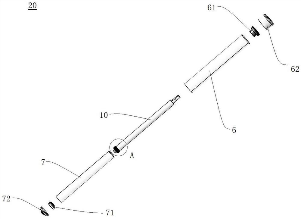
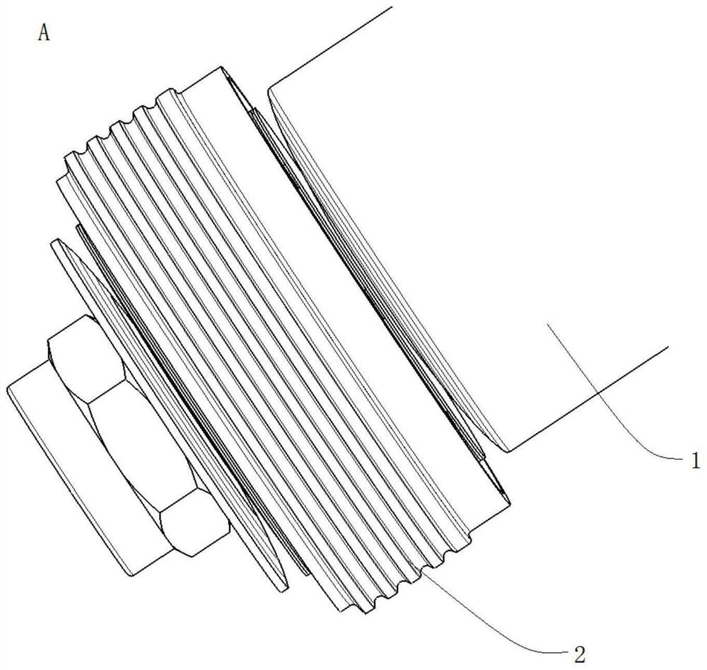
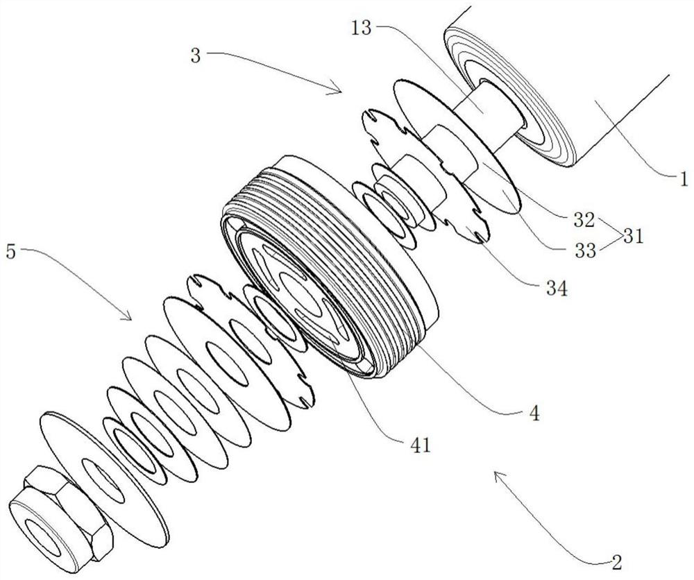
Piston valve system, shock absorber provided with piston valve system and vehicle

A technology of piston valve and shock absorber, applied in the direction of shock absorber, shock absorber, spring/shock absorber, etc., can solve the problem of increasing the axial length of the piston valve system, affecting the steering stability of the vehicle, and redundancy of the piston valve system. Increase and other problems to achieve the effect of reducing the axial length and weight, simplifying the structure, improving performance and life stability

Inactive Publication Date: 2021-06-08
QOROS
View PDF9 Cites 0 Cited by
  • Summary
  • Abstract
  • Description
  • Claims
  • Application Information

AI Technical Summary

Problems solved by technology

[0002] The piston valve system in the current shock absorber is generally provided with a valve plate support block at both ends of the valve plate assembly, which will lead to an increase in the redundancy of the piston valve system, an increase in the axial length and weight of the piston valve system
And as the shock absorber is used longer, it will also lead to deformation and failure of the valve plate, which will lead to the deterioration of the performance of the shock absorber and affect the handling stability of the vehicle.

Method used


Image

  • Piston valve system, shock absorber provided with piston valve system and vehicle
  • Piston valve system, shock absorber provided with piston valve system and vehicle
  • Piston valve system, shock absorber provided with piston valve system and vehicle

Examples


Embodiment Construction

[0027] Embodiments of the present invention will be described in detail below, and examples of the embodiments are illustrated in the drawings, in which the same or similar reference numerals represent the same or similar elements or elements having the same or similar functions. The following is exemplary, and is intended to be used to illustrate the invention without understanding the limitation of the invention.

[0028] In the description of the present invention, it is to be understood that the term "longitudinal", "horizontal", "length", "width", "thickness", "upper", ",", "front", "post", " Left "," Right "," Right "," Level "," Top "," Bottom "," Inside "," Out ", the orientation is based on the orientation or positional relationship shown in the drawing. It is intended to facilitate the description of the present invention and simplified description, rather than indicating or implying that the device or element must have a specific orientation, and is constructed in a par...


PUM


Abstract

The invention discloses a piston valve system, a shock absorber provided with the piston valve system and a vehicle. The piston valve system comprises a piston rod and a valve plate assembly. A valve plate deformation supporting part and a valve plate inner supporting part protruding downwards are formed on the lower end face of the piston rod, a valve plate shaft is arranged at the position of the valve plate inner supporting part, and the valve plate deformation supporting part is located on the periphery of the valve plate inner supporting part. The valve plate assembly is arranged on the valve plate shaft in a sleeving manner and provided with a compression valve plate, the compression valve plate comprises a compression joint part in compression joint with the valve plate inner supporting part and a deformation part located on the periphery of the compression joint part, and the deformation part is provided with a deformation position making contact with the valve plate deformation supporting part and a free position separated from the valve plate deformation supporting part. According to the piston valve system, the function of a compression supporting block used for supporting the compression valve plate is integrated at the lower end of the piston rod, and therefore the number of components of the piston valve system can be reduced, the axial length and weight of the piston valve system can be reduced, and it is guaranteed that the piston valve system is simple in structure, compact and low in cost.

Description

Technical field [0001] The present invention relates to the field of damper, and in particular, in particular, a piston valve system and a damper and a vehicle mounted with the piston valve. Background technique [0002] The piston valve system in the current damper is typically disposed in each of the two ends of the valve assembly, which results in a redundancy increase of the piston valve system, and the axial length of the piston valve and increases by weight. And as the time to the damper is increased, the valve is deformable, resulting in deterioration of the performance of the damper, affecting the manipulation stability of the vehicle. Inventive content [0003] The present invention is intended to solve one of the technical problems in the prior art at least to some extent. To this end, the present invention proposes a piston valve, which integrates a valve support block to ensure a compact structure of the piston valve, and has high work reliability. [0004] The prese...

Claims


Application Information

Patent Timeline
Patent Type & Authority Applications(China)
IPC IPC(8): F16F9/34F16F9/32
CPCF16F9/34F16F9/3221F16F9/3214
Inventor 刘旭晖刘国兵
Owner QOROS
Why Eureka
Try Eureka