
Tooth mold alignment method, tooth structure, three-dimensional model alignment method and structural member

A tooth model and tooth technology, applied in the field of three-dimensional tooth model alignment method and tooth structure, three-dimensional model alignment method and structural parts, can solve the problems of splicing failure, alignment failure, incorrect point cloud search corresponding point and so on

Active Publication Date: 2021-06-08
INTERFACE TECH CHENGDU CO LTD +3
View PDF6 Cites 3 Cited by
  • Summary
  • Abstract
  • Description
  • Claims
  • Application Information

AI Technical Summary

Problems solved by technology

[0004] However, for complex models, the tooth model or animation model is taken as an example for small models, and the mechanical model is taken as an example for large models. The number represents the rotation relationship; or the covariance matrix is ​​subjected to Singular Value Decomposition (Singular Value Decomposition, SVD) to obtain the final rotation matrix; but when it is applied to the two-sided or multi-faceted combination of a complex model, such as when the tooth model is occluded, due to The coincidence problem of point clouds is difficult to register, that is, it is impossible to achieve fast and accurate stitching results, and usually the stitching fails due to the following reasons: when the distance between point clouds is large, it is easy to fail to align, and the initial search of point clouds corresponds to incorrect points cause the alignment to fail

Method used


Image

  • Tooth mold alignment method, tooth structure, three-dimensional model alignment method and structural member
  • Tooth mold alignment method, tooth structure, three-dimensional model alignment method and structural member
  • Tooth mold alignment method, tooth structure, three-dimensional model alignment method and structural member

Examples


Embodiment Construction

[0040] In order to make the above-mentioned purpose, features and advantages of the present application more obvious and understandable, the specific implementation manners of the present application will be described in detail below in conjunction with the accompanying drawings. In the following description, numerous specific details are set forth in order to provide a thorough understanding of the application. However, the present application can be implemented in many other ways different from those described here, and those skilled in the art can make similar improvements without departing from the connotation of the present application, so the present application is not limited by the specific embodiments disclosed below.

[0041] It should be noted that when a component is referred to as being “fixed on” or “set on” another component, it may be directly on the other component or there may also be an intervening component. When a component is said to be "connected" to anoth...


PUM


Abstract

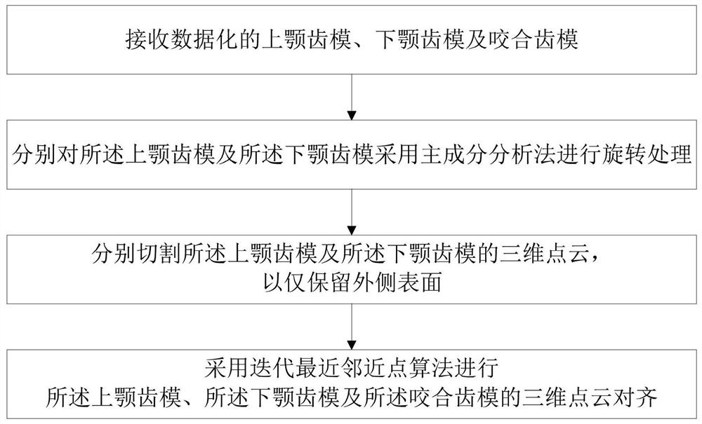
The invention relates to a three-dimensional tooth mold alignment method, a tooth structure, a three-dimensional model alignment method and a structural member. The three-dimensional tooth mold alignment method comprises the following steps: receiving a digitized upper jaw tooth mold, a digitized lower jaw tooth mold and a digitized occlusion tooth mold; carrying out rotation treatment to the upper jaw tooth mold and the lower jaw tooth mold through a principal component analysis method; cutting the three-dimensional point cloud of the upper jaw tooth mold and the three-dimensional point cloud of the lower jaw tooth mold, so that only the outer side surfaces are reserved; and carrying out three-dimensional point cloud alignment on the upper jaw tooth mold, the lower jaw tooth mold and the occlusion tooth mold by adopting an iterative nearest neighbor point algorithm. According to the three-dimensional tooth mold alignment method, by optimizing the cutting mode, on one hand, the distance between the point clouds can be shortened, and on the other hand, the initial search corresponding points of the point clouds can be accurately positioned, so that the alignment success rate of the three-dimensional point clouds is greatly improved; and moreover, only the outer side surfaces are reserved, so that the calculation amount for calculating alignment by an iterative algorithm is simplified, and a rapid and accurate splicing effect can be achieved.

Description

technical field [0001] The application relates to the field of three-dimensional model manufacturing, in particular to a three-dimensional tooth mold alignment method and a tooth structure, a three-dimensional model alignment method and structural parts. Background technique [0002] The point data set on the surface of the product obtained by measuring instruments is called a point cloud. After using a camera or other methods to obtain the three-dimensional (3-dimension, 3D) point cloud of the object, due to different acquisition devices and shooting angles Influenced by different objective factors, even the point cloud obtained by the same object at the same shooting position will have large differences, mainly due to changes in rotation or translation. For two images in a set of image data sets, it is necessary to find a spatial transformation to map one image to another image, so that the points corresponding to the same spatial position in the two images are one-to-one,...

Claims


Application Information

Patent Timeline
Patent Type & Authority Applications(China)
IPC IPC(8): G06T19/20A61C13/34
CPCG06T19/20A61C13/34G06T2219/2004G06T2219/2016Y02P90/30
Inventor 陈威宁魏福呈廖致霖
Owner INTERFACE TECH CHENGDU CO LTD
Learn More