Protective tooth
A technology of a main body part and a supporting part, which can be applied to other nursing equipment, snoring prevention devices, non-surgical orthopedic operations, etc., can solve the problems of the main body of the mouthguard, the deformation of the main body of the mouthguard, and the inability to adequately limit the displacement of the mandible.
- Summary
- Abstract
- Description
- Claims
- Application Information
AI Technical Summary
Problems solved by technology
Method used
Image
Examples
no. 1 approach
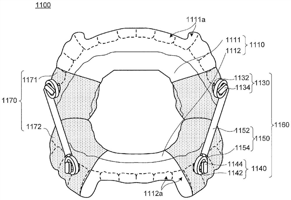
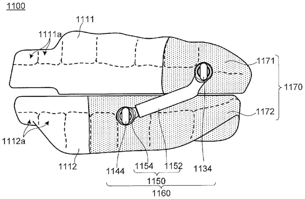
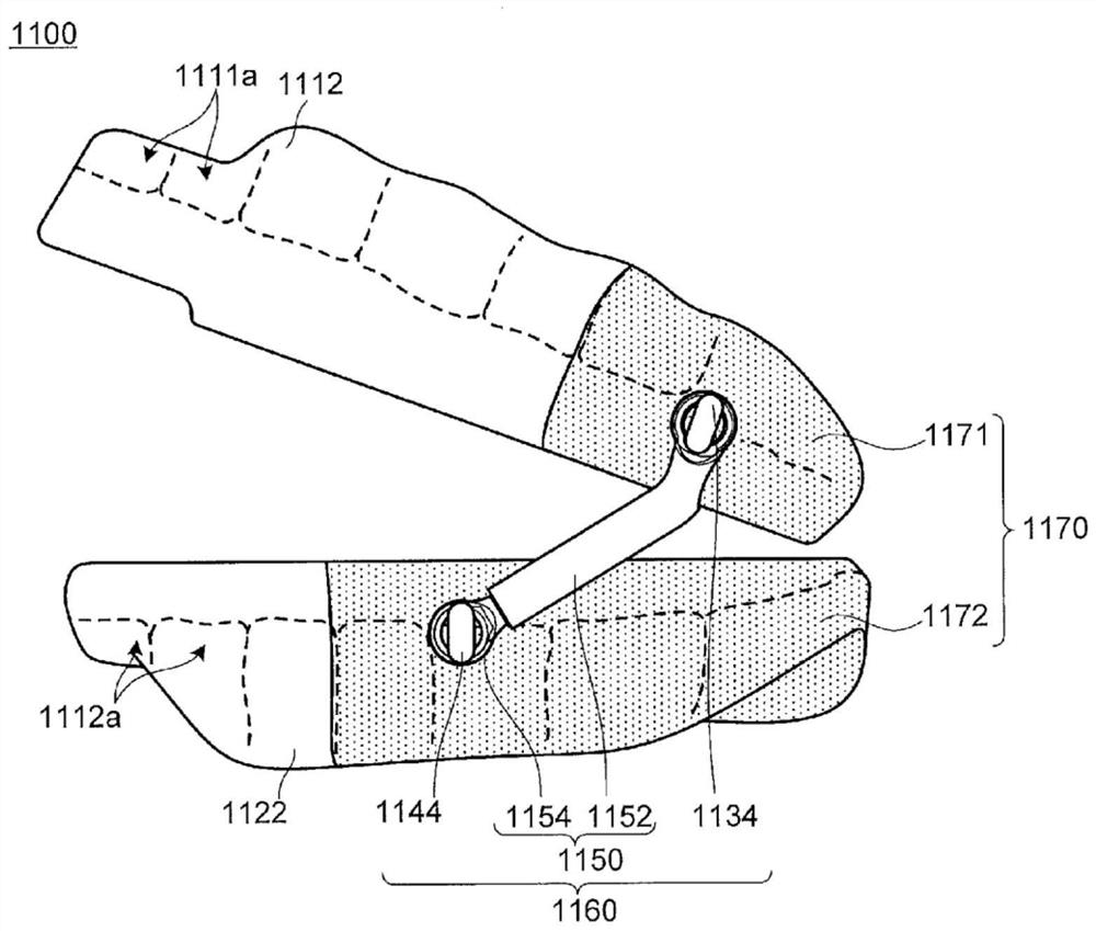
[0028] figure 1 is a schematic front view of a mouthpiece 1100 according to a first embodiment of the present invention, Figure 2A is a schematic side view of the mouthguard 1100 with the mouth closed, Figure 2B It is a schematic side view when the mouthpiece 1100 is opened. Such as figure 1 , Figure 2A and Figure 2B As shown, the mouthpiece 1100 of this embodiment has: a pair of mouthpiece body parts 1110, composed of an upper mouthpiece body part 1111 and a mandibular mouthpiece body part 1112; The displacement of the tooth body part 1112 to the rear; and the support part 1170, including a pair of left and right upper support parts 1171 and a pair of left and right lower support parts 1172, the upper support part 1171 covers a part of the upper jaw mouthguard body part 1111 and uses For supporting the positioning component 1160 , the lower support portion 1172 covers a part of the mandibular mouthguard main body 1112 and is used for supporting the positioning compon...
no. 2 approach
[0095] Figure 3A It is a schematic perspective view which shows the structure of the upper jaw side of the mouthpiece 2100 of 2nd Embodiment of this invention, Figure 3B It is a schematic perspective view which shows the structure of the mandibular side of this mouthpiece 2100. and, Figure 4 is a side view of the mouthguard 2100 with the mouth closed. Such as Figure 3A , Figure 3B and Figure 4 As shown, the mouthpiece 2100 of this embodiment has: a pair of mouthpiece body parts 1110, which are composed of an upper mouthpiece body part 1111 and a lower jaw mouthpiece body part 1112; A pair of left and right stoppers 2130 and a pair of left and right movable wings 2160 arranged on the side of the mandibular mouthguard main body 1112; The support part 2172, the upper support part 2171 is used to cover a part of the upper mouthpiece body part 1111 and supports the stopper 2130, and the lower support part 2172 is used to cover a part of the lower mouthpiece body part 11...
no. 3 approach
[0122] Figure 5 is a schematic perspective view of a mouthpiece 3100 according to a third embodiment of the present invention, Figure 6 is a schematic side view of the mouthpiece 3100 when the mouth is closed. Such as Figure 5 and Figure 6 As shown, it has: a pair of mouthpiece main body 1110, which is composed of an upper mouthpiece main body 1111 and a lower jaw mouthpiece main body 1112; a positioning component 3160, used to limit the rearward displacement of the lower jaw mouthpiece main body 1112; and a support part 3170, including an upper supporting part 3171 and a pair of upper and lower supporting parts 3172, the upper supporting part 3171 is used to cover a part of the upper mouthpiece body part 1111 and supports the positioning part 3160, and the lower supporting part 3172 is used to cover Part of the lower mouthpiece body portion 1112 and supports the positioning member 3160 .
[0123] In the mouthpiece 3100 of this embodiment, the positioning member 3160 r...
PUM
| Property | Measurement | Unit |
|---|---|---|
| Density | aaaaa | aaaaa |
| Tensile strength | aaaaa | aaaaa |
| Density | aaaaa | aaaaa |
Abstract
Description
Claims
Application Information
 - R&D
- Intellectual Property
- Life Sciences
- Materials
- Tech Scout
- Unparalleled Data Quality
- Higher Quality Content
- 60% Fewer Hallucinations
Browse by: Latest US Patents, China's latest patents, Technical Efficacy Thesaurus, Application Domain, Technology Topic, Popular Technical Reports.
© 2025 PatSnap. All rights reserved.Legal|Privacy policy|Modern Slavery Act Transparency Statement|Sitemap|About US| Contact US: help@patsnap.com


