
Novel magnetic-resistance-type electromagnetic clutch

An electromagnetic clutch, reluctance technology, applied in electric brake/clutch, asynchronous induction clutch/brake, electrical components, etc., can solve the problems of reduced service life, large volume torque, degraded magnetic performance, etc., to achieve service life length, increase the amount of magnetoresistance change, and improve the effect of bonding torque

Pending Publication Date: 2017-10-24
李亚涛
View PDF1 Cites 0 Cited by
  • Summary
  • Abstract
  • Description
  • Claims
  • Application Information

AI Technical Summary

Problems solved by technology

[0002] At present, in the flight control systems of some aircrafts in Russia and my country, small magnetic powder clutches are usually used. Because the magnetic powder of the magnetic powder clutch enters the running bearing, the bearing will be stuck, and the magnetic powder will rub against each other in the clutch. can deteriorate, lead to coagulation, agglomeration, cause failure, and greatly reduce the service life; and (ZL201210078990.1) patent, the reluctance eddy current electromagnetic clutch is a special micro-motor in essence, and the reluctance eddy current electromagnetic clutch is a single breath Reluctance, low motor coefficient, large volume and small torque, in order to improve flight reliability and safety, therefore, it is necessary to improve

Method used


Image

  • Novel magnetic-resistance-type electromagnetic clutch
  • Novel magnetic-resistance-type electromagnetic clutch
  • Novel magnetic-resistance-type electromagnetic clutch

Examples


Embodiment Construction

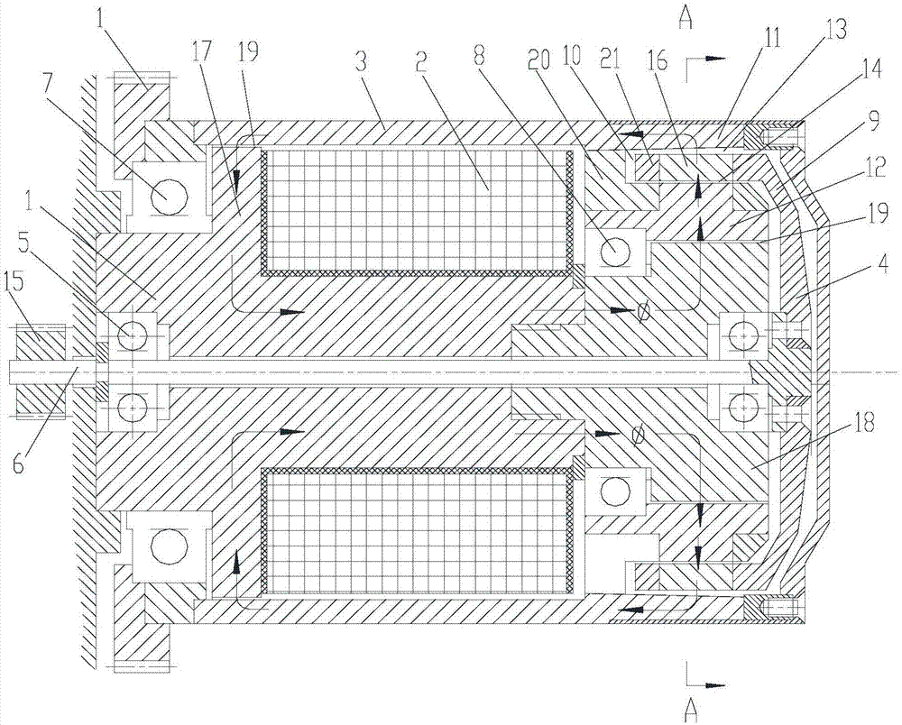
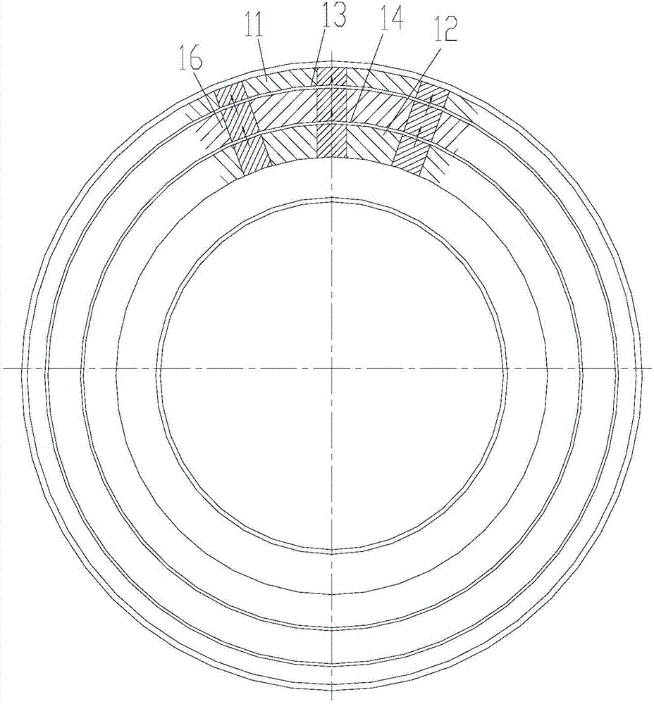
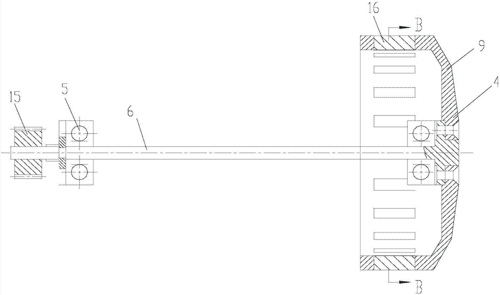
[0021] Attached below Figure 1-7 An embodiment of the present invention is described.

[0022] The new reluctance electromagnetic clutch has a stator 1, a winding 2 and a rotor. The rotor includes a driving rotor 3 and a driven rotor 4. The stator 1 is supported on the output shaft 6 of the driven rotor 4 through a bearing I5 and driven The rotor disk 9 on the rotor 4 is inserted into the annular space 10 on the active rotor disk 3, the active rotor 3 is supported on the outer circumference of the stator 1 through the bearing II7 and the bearing III8 and the winding 2 sleeved on the stator 1 is placed on the stator 1 and the driving rotor 3, specifically, the stator 1 is composed of a left stator 17 and a right stator 18, and the left stator 17 and the right stator 18 are connected and supported on the output shaft 6 through a bearing I5, The left side and the right side of the active rotor 3 are respectively supported on the outer circumference of the left stator 17 and the...


PUM


Abstract

The invention provides a novel magnetic-resistance-type electromagnetic clutch. The clutch possesses a stator, a winding and a rotor. The rotor comprises an active rotor and a driven rotor. The stator is supported on an output shaft of the driven rotor through a bearing I and a rotor disk on the driven rotor is inserted into an annular space of an active rotor disk. The active rotor is supported on an outer circumference of the stator through a bearing II and a bearing III and the winding sleeving the stator is placed between the stator and the active rotor. The annular space is formed by upper jaw teeth and lower jaw teeth, the upper jaw teeth and the lower jaw teeth are provided with a same number of teeth and the teeth correspond to each other. The teeth, which are embedded into the rotor disc, correspond to the upper jaw teeth and the lower jaw teeth, and are inserted into the annular space. In the invention, a problem that magnetic performance of a magnetic powder type clutch becomes poor due to mutual friction and aging so that condensation, agglomeration or magnetic powder leakage are generated and a bearing is stuck and other problems are solved, the structure is simple, a service life is long, reliability and safety of flight are increased, and a combined torque and a combined speed are greatly improved.

Description

technical field [0001] The invention belongs to the technical field of aircraft automatic control, and in particular relates to a novel reluctance type electromagnetic clutch, which is used in an executive mechanism of an airborne aircraft automatic control system. Background technique [0002] At present, in the flight control systems of some aircrafts in Russia and my country, small magnetic powder clutches are usually used. Because the magnetic powder of the magnetic powder clutch enters the running bearing, the bearing will be stuck, and the magnetic powder will rub against each other in the clutch. can deteriorate, lead to coagulation, agglomeration, cause failure, and greatly reduce the service life; and (ZL201210078990.1) patent, the reluctance eddy current electromagnetic clutch is a special micro-motor in essence, and the reluctance eddy current electromagnetic clutch is a single breath Reluctance, low motor coefficient, large volume and small torque, in order to impr...

Claims


Application Information

Patent Timeline
Patent Type & Authority Applications(China)
IPC IPC(8): H02K49/04
CPCH02K49/043
Inventor 李亚涛
Owner 李亚涛
Learn More