A lightning arrester with adjustable discharge gap
A discharge gap and lightning arrester technology, applied in the field of lightning arresters, can solve problems such as the unadjustable discharge gap, achieve good arc extinguishing effect, quick and convenient installation, and improve the effect of lightning protection and dredging function.
- Summary
- Abstract
- Description
- Claims
- Application Information
AI Technical Summary
Problems solved by technology
Method used
Image

Examples
Embodiment 1
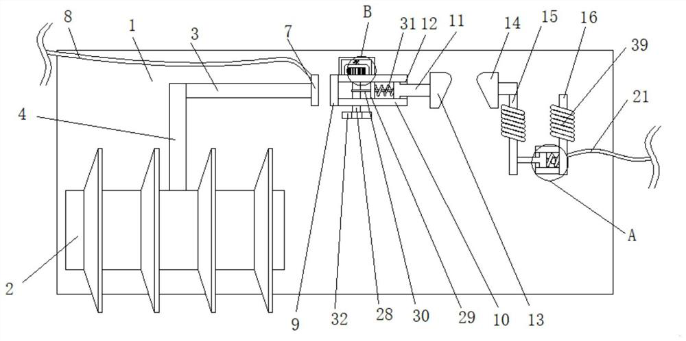
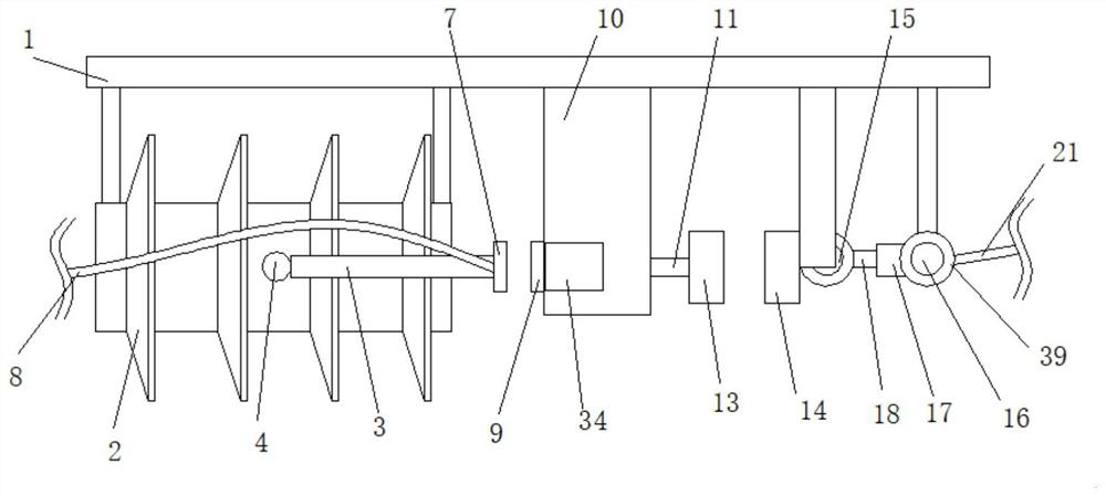
[0033] Embodiment one, such as Figure 1-8As shown, a lightning arrester with adjustable discharge gap includes a vertically arranged insulating plate 1, one side of the insulating plate 1 is fixedly connected with an insulator 2, the insulator 2 is arranged horizontally, and a first connecting rod 3 is arranged horizontally above the insulator 2 One end of the first connecting rod 3 close to the insulator 2 is fixedly connected with a vertically arranged second connecting rod 4, the upper surface of the insulator 2 is provided with a connecting groove 5, the bottom end of the second connecting rod 4 is inserted into the connecting groove 5, and the connecting groove 5 A connection mechanism 6 is provided inside, the first auxiliary electrode plate 7 is fixedly connected to the end of the first connecting rod 3 away from the insulator 2, the first auxiliary electrode plate 7 is fixedly connected to a connecting wire 8, and the first auxiliary electrode plate 7 is far away from ...
Embodiment 2
[0034] Embodiment two, such as Figure 4 , 8 As shown, the connection mechanism 6 includes a groove 22 arranged in the connecting groove 5, the groove 22 is arranged horizontally, and a sliding piece 23 is slidably connected in the groove 22, and the sliding piece 23 is connected to the groove 22 by the second spring 24 arranged horizontally. The inner wall is fixedly connected, and the end of the sliding piece 23 facing the outside of the groove 22 is fixedly connected with a clamping block 25 , the side of the bottom end of the second connecting rod 4 is provided with a clamping groove 26 that fits with the clamping block 25 , and the clamping block 25 is far away from the inner side of the groove 22 One end is hemispherical, the slot 26 is a hemispherical shape matching the block 25, the inner port of the groove 22 is fixedly connected with a limit ring 27, and the limit ring 27 is sleeved on the block 25 and slidably connected with it, The assembly of the second connectin...
Embodiment 3
[0035] Embodiment three, such as Figure 4 , 8 As shown, the bottom end of the second connecting rod 4 is in an inverted conical shape, and the bottom end of the connecting groove 5 is located in the inverted conical shape that matches the second connecting rod 4, so that the second connecting rod 4 can push the block 25 back to the groove 22 Inside, the connection between the second connecting rod 4 and the connecting groove 5 is more convenient.
PUM
 Abstract
Description
Claims
Application Information