Door plate opening structure based on outdoor wall-mounted box

A door panel and chassis technology, which is applied in the field of door panel opening structure based on outdoor wall-mounted boxes, can solve the problems affecting the normal work of maintenance workers and the door panel of the wall-mounted box cannot be fixed, and achieves the effects of simple structure, guaranteed heat dissipation, and convenient use

Inactive Publication Date: 2021-06-08
XIAN XINGYUN NETWORK
View PDF0 Cites 0 Cited by
  • Summary
  • Abstract
  • Description
  • Claims
  • Application Information

AI Technical Summary

Problems solved by technology

[0005] The invention provides an outdoor wall-mounted case that is easy to disassemble, which solves the problem that the position cannot be fixed when the door panel of the wall-mounted case is opened, which affects the normal work of maintenance workers.

Method used


Image

  • Door plate opening structure based on outdoor wall-mounted box
  • Door plate opening structure based on outdoor wall-mounted box
  • Door plate opening structure based on outdoor wall-mounted box

Examples


Embodiment 1

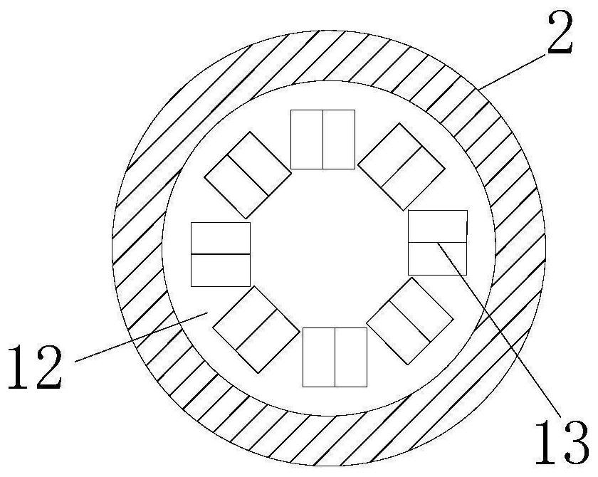
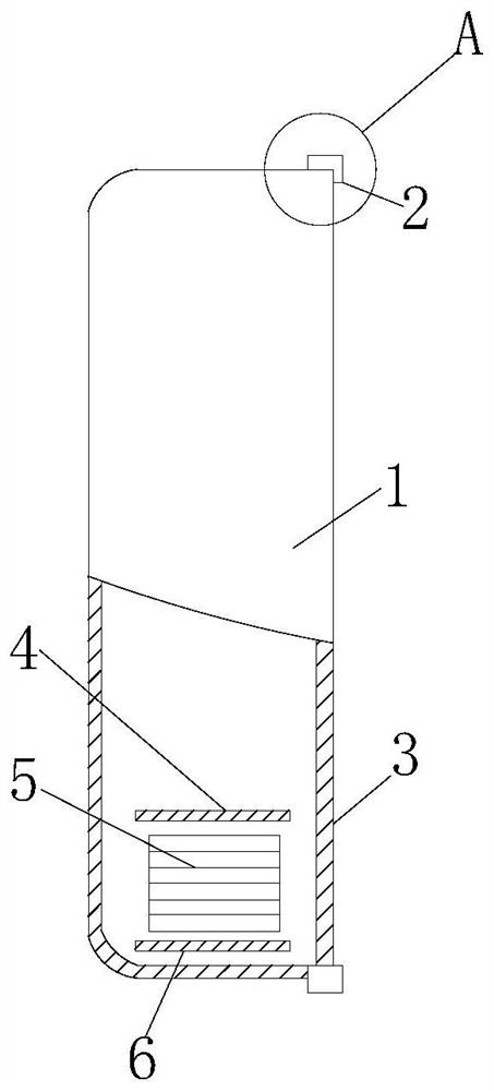
[0022] see Figure 1-4 , the present invention provides a door panel opening structure based on an outdoor wall-mounted box, including a chassis 1, an opening is opened on the side of the chassis 1 away from the wall, and two vertically placed and mutually symmetrical installations are fixedly installed on the side of the opening on the chassis 1. Block 2, the insides of the two mounting blocks 2 are provided with cylindrical grooves 12, and the insides of the two cylindrical grooves 12 are movably installed with a turntable 8 matching the cylindrical groove 12, and the two turntables 8 are located opposite to each other. One side of each side is fixedly installed with rotating rod 7, and the side opposite to each other on the mounting block 2 is provided with openings suitable for rotating rod 7, and the two openings are connected with the outside world. A door panel 3 is fixedly installed between the two turntables 8, and balls 11 are movably installed on the two turntables ...

Embodiment 2

[0027] see image 3 and Figure 4 , this embodiment is further optimized on the basis of Embodiment 1, specifically, vents 5 are symmetrically opened on both sides of the cabinet 1 perpendicular to the door panel 3, and the inside of the cabinet 1 is located at the vents 5. Rain protection mechanism.

[0028] In this embodiment, the rain-shielding mechanism includes an upper baffle 4 and a lower baffle 6 fixedly installed on the inner wall of the chassis 1 at the vent 5, the upper baffle 4 and the lower baffle 6 are both L-shaped, and the lower baffle 6 includes Hold the upper baffle 4, and an air duct is formed between the upper baffle 4 and the lower baffle 6, the width of the upper baffle 4 and the lower baffle 6 are all adapted to the width of the inner wall of the cabinet 1, and the lower baffle 6 and the chassis A water tank 14 is formed between the inner walls of the cabinet 1, and a water outlet pipe 15 is connected between the bottom of the water tank 14 and the out...


PUM


Abstract

The invention provides a door plate opening structure based on an outdoor wall-mounted box. The door plate opening structure based on the outdoor wall-mounted box comprises a machine box, an opening is formed in the side, away from a wall, of the machine box, two mounting blocks which are vertically placed and symmetrical are fixedly mounted on the side, located on the opening, of the machine box, and cylindrical grooves are formed in the two mounting blocks correspondingly; and balls are movably installed on the two rotating discs, the balls do not coincide with the center positions of the end faces of the rotating discs, and the balls are attached to the inner walls of the cylindrical grooves. Movable blocks are arranged in spring grooves, and the balls are clamped and movably mounted on the movable blocks, so that when the door plate is rotated, the balls roll from the interior of one triangular prism groove to the interior of the adjacent triangular prism groove, and the springs are compressed and then released during the period, so that the door plate is subjected to resistance during rotation; and due to the existence of the resistance, the door plate cannot be pushed at will.

Description

technical field [0001] The invention relates to the technical field of wall-mounted cabinet equipment, in particular to an opening structure based on an outdoor wall-mounted cabinet door panel. Background technique [0002] The power distribution cabinet (box) is divided into power distribution cabinet (box), lighting distribution cabinet (box), metering cabinet (box), and is the final equipment of the power distribution system. The power distribution cabinet is a general term for the motor control center. The power distribution cabinet is used in the occasions where the load is relatively scattered and there are few circuits; the motor control center is used in the occasions where the load is concentrated and there are many circuits. They distribute the electric energy of a certain circuit of the upper-level power distribution equipment to the nearest load. This level of equipment shall provide protection, monitoring and control of the load. [0003] Nowadays, many power...

Claims


Application Information

Patent Timeline
Patent Type & Authority Applications(China)
IPC IPC(8): H02B1/44E05C17/54E05D11/10H02B1/56H02B1/28
CPCE05C17/54E05D11/1028E05D2011/1035H02B1/28H02B1/44H02B1/565
Inventor 吴新潮韩文彬
Owner XIAN XINGYUN NETWORK
Why Eureka
Try Eureka