A device for measuring the working distance of a corneal topograph

A technology of corneal topography and working distance, which is applied in the fields of testing optical performance, eye testing equipment, medical science, etc., can solve the problems of corneal curvature radius restoration uncertainty, etc., and achieve the effect of accurate diagnosis and high restoration precision

Active Publication Date: 2022-01-04
NINGBO MING SING OPTICAL R & D
View PDF6 Cites 0 Cited by
  • Summary
  • Abstract
  • Description
  • Claims
  • Application Information

AI Technical Summary

Problems solved by technology

[0003] In general corneal topographs, in order to clearly capture the apex of the cornea and the surrounding cornea, and to keep the magnification β constant, an object space telecentric lens is often used, which is characterized by a larger object space Depth of field, so when collecting images, clear images can also be captured under different working distances (that is, the distance from the corneal apex to the first lens), but it brings great uncertainty to the restoration of the final corneal curvature radius Therefore, in order to improve the restoration accuracy of the corneal curvature, it is necessary to determine a more accurate value of the working distance

Method used


Image

  • A device for measuring the working distance of a corneal topograph
  • A device for measuring the working distance of a corneal topograph

Examples


Embodiment 1

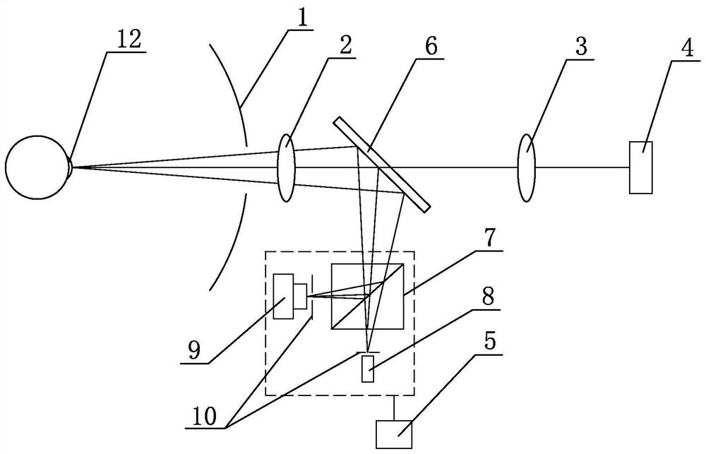
[0018] Embodiment 1: As shown in the figure, a measuring device for the working distance of a corneal topograph includes a corneal photographing assembly and a distance measuring optical path assembly. The corneal photographing assembly includes a coaxial and sequentially arranged placido disc 1 and a first lens 2 , the second lens 3 and the first photodetector 4, the ranging optical path assembly includes a beam splitting unit, a transmitting and receiving unit and a drive motor 5, the beam splitting unit is a beam splitter 6, the beam splitter 6 is coaxial with the placido disc 1, and the beam splitter The mirror 6 is arranged between the first lens 2 and the second lens 3, and is used for transmitting the light entering the cornea photographing assembly and reflecting the light entering the transmitting and receiving unit. The transmitting and receiving unit includes a dichroic prism 7, a light source 8 and a second photoelectric The detector 9, the light source 8 and the se...

Embodiment 2

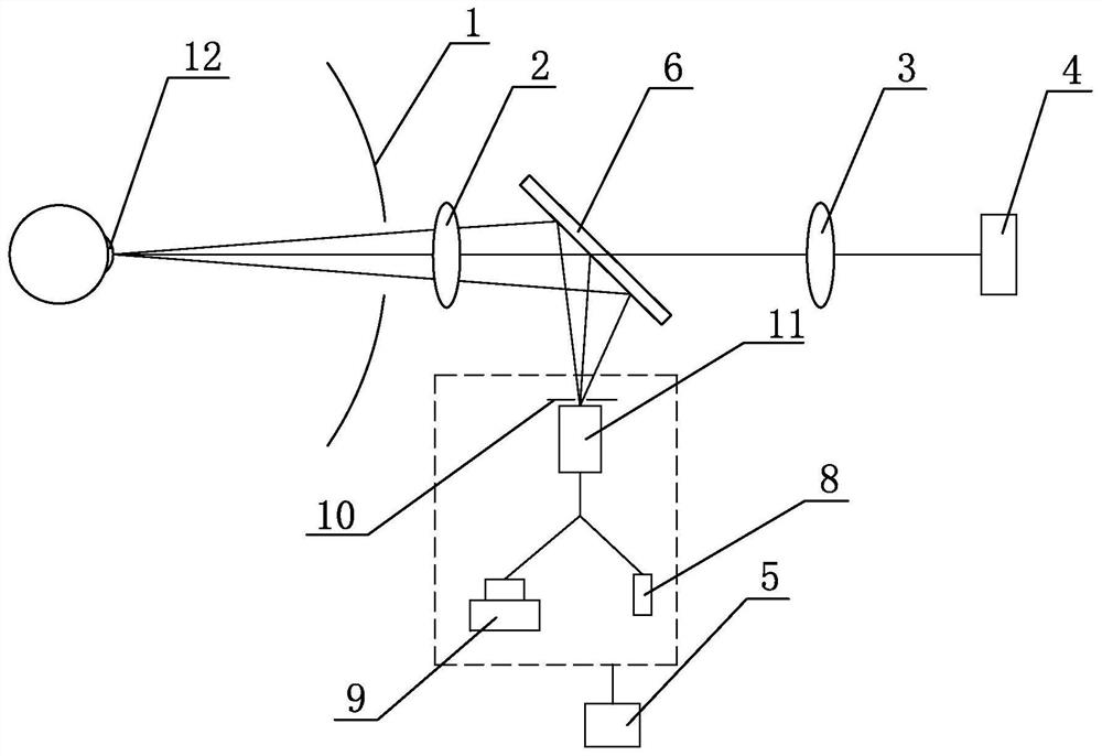
[0019] Embodiment two: as shown in the figure, other structures are the same as embodiment one, and the difference is that the transmitting and receiving unit includes a light splitting device 11, a light source 8 and a second photodetector 9 in a Y-shaped distribution, and at the port of the light splitting device 11 A diaphragm 10 is provided.

[0020] In the first and second embodiments above, the second photodetector 9 is a photomultiplier tube (PMT) or an avalanche photodiode (APD), and the light source 8 adopts a low-power infrared band laser with a power <5mw and a wavelength of 780nm; the aperture is 10 The diameter is less than 0.3mm; the first photodetector 4 is an area array photodetector, such as: CCD or CMOS.


PUM


Abstract

The invention discloses a working distance measuring device and measuring method of a corneal topography instrument, which is characterized in that it includes a corneal photographing component and a distance measuring optical path component. Two lenses and the first photodetector, the distance measuring optical path assembly includes a beam splitting unit, a transmitting and receiving unit and a drive motor, the beam splitting unit is arranged on the optical axis of the cornea photographing assembly, and the beam splitting unit is located between the first lens and the second lens Between, for the light transmitted into the cornea photographing assembly and the light reflected into the transmitting and receiving unit, the driving motor is used to drive the transmitting and receiving unit to move back and forth along the direction perpendicular to the optical axis of the corneal photographing assembly; the advantage is that through this The measuring device and method can accurately measure the working distance of the corneal topographer when photographing the cornea, so that the restoration accuracy of the corneal curvature is higher, thereby making the diagnosis of corneal diseases more accurate by the corneal topographer.

Description

technical field [0001] The invention relates to a corneal topography instrument for inspecting the cornea, in particular to a measuring device for the working distance of the corneal topography instrument. Background technique [0002] The corneal topography instrument based on the Placido (Placido's) disc has diopter visualization, can draw various topographic maps of the cornea more accurately, can diagnose a variety of corneal diseases, and guide various corneal operations effectively. It has many advantages such as diverse measurement data and strong analysis ability, and it is very popular in the medical market. [0003] In general corneal topographs, in order to clearly capture the apex of the cornea and the surrounding cornea, and to keep the magnification β constant, an object space telecentric lens is often used, which is characterized by a larger object space Depth of field, so when collecting images, clear images can also be captured under different working dista...

Claims


Application Information

Patent Timeline
Patent Type & Authority Patents(China)
IPC IPC(8): A61B3/107A61B3/14G01M11/02
CPCA61B3/107A61B3/14G01M11/02
Inventor 黄涨国马孟鸿沃圣杰梅建国骆晟毛维波
Owner NINGBO MING SING OPTICAL R & D
Why Eureka
Try Eureka