A drainage collection device
A collection device and collection cover technology, which is applied in the fields of suction equipment, inoculation and ovulation diagnosis, medical science, etc., can solve the problems of frequent replacement of gauze, increase of nursing workload and cost, stoma infection, etc., and achieve the effect of convenient detection and analysis
- Summary
- Abstract
- Description
- Claims
- Application Information
AI Technical Summary
Problems solved by technology
Method used
Image
Examples
specific Embodiment approach 1
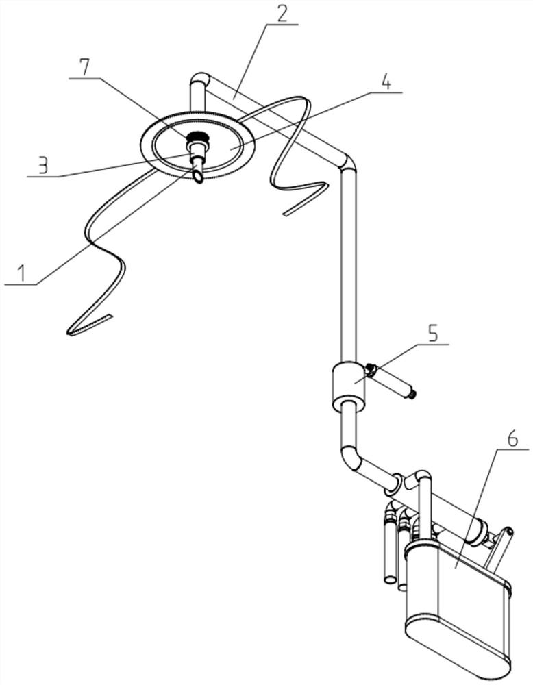
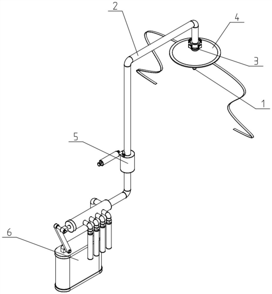
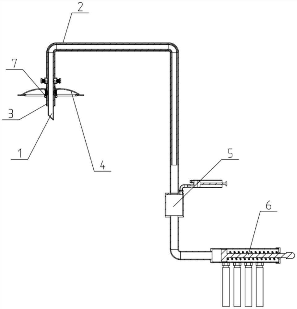
[0040] Such as Figure 1-12 As shown, a drainage collection device includes an inner drainage tube 1, an outer drainage tube 2, a plugging tube 3, an umbrella-shaped seepage collection cover 4, a negative pressure mechanism 5 and a drainage fluid collection mechanism 6; the plugging tube 3 One end of the external drainage tube 2 is fixedly connected to one end; the other end of the external drainage tube 2 is fixedly connected to and communicated with one end of the negative pressure mechanism 5; the other end of the negative pressure mechanism 5 is connected to the drainage The liquid collection mechanism 6 is fixedly connected and communicated; the inner drainage tube 1 is co-located on the inner side of the outer drainage tube 2 and the blocking tube 3, and the head end of the inner drainage tube 1 passes through to the blocking tube. The outer end of the tube 3, the seepage diversion area is formed between the inner drainage tube 1, the outer drainage tube 2 and the blocki...
specific Embodiment approach 2
[0043] Such as Figure 1-12 As shown, the described drainage collection device also includes a blocking air bag 7; To block.
[0044] The setting of the blocking air bag 7 is used to improve the blocking effect of the blocking tube 3 on the opening of the skin and reduce the amount of seepage.
[0045] The blocking air bag 7 includes a fixed ring 701, a tension spring 702, a movable ring 703 and an inner annular air bag 704; the fixed ring 701 is fixed on the blocking tube 3, and is located in the umbrella-shaped seepage collection The inner side of the cover 4; the movable ring 703 is slidably fitted on the blocking tube 3; the movable ring 703 and the fixed ring 701 are fixedly connected by a tensioning compression spring 702, and the tensioning compression spring 702 is sleeved On the blocking tube 3; the fixed ring 701 is located between the umbrella-shaped seepage collection cover 4 and the movable ring 703; the inner annular air bag 704 is fixedly connected to the mova...
specific Embodiment approach 3
[0047] Such as Figure 1-12 As shown, the external drainage tube 2 includes a cylindrical diversion box 201, a flexible connecting pipe 202 and a limit assembly 203; the circular through holes at both ends of the cylindrical diversion box 201 are respectively connected with the plugging tube 3 and the The flexible connecting pipe 202 is sealed and fixedly connected and communicated; the flexible connecting pipe 202 is fixedly connected and communicated with one end of the negative pressure mechanism 5; the diameter of the cylindrical diversion box 201 is larger than that of the flexible connecting pipe 202 diameter and the diameter of the plugging tube 3; the side of the cylindrical diversion box 201 is uniformly surrounded by four stop components 203, and the inner sides of the four limit components 203 are press-fitted to the four sides of the inner drainage tube 1. side;
[0048] The size setting of the cylindrical diversion box 201 inside the outer drainage tube 2 can pre...
PUM
 Abstract
Description
Claims
Application Information
 - R&D
- Intellectual Property
- Life Sciences
- Materials
- Tech Scout
- Unparalleled Data Quality
- Higher Quality Content
- 60% Fewer Hallucinations
Browse by: Latest US Patents, China's latest patents, Technical Efficacy Thesaurus, Application Domain, Technology Topic, Popular Technical Reports.
© 2025 PatSnap. All rights reserved.Legal|Privacy policy|Modern Slavery Act Transparency Statement|Sitemap|About US| Contact US: help@patsnap.com


