Drainage collecting device

A collection device and collection cover technology, which is applied in the fields of suction equipment, ovulation diagnosis, medical science, etc., can solve the problems of frequent replacement of gauze, stimulation of drainage tube skin, increase of nursing workload and nursing cost, etc., and achieve the convenience of detection and analysis Effect

Active Publication Date: 2021-06-11
THE AFFILIATED HOSPITAL OF QINGDAO UNIV
View PDF12 Cites 2 Cited by
  • Summary
  • Abstract
  • Description
  • Claims
  • Application Information

AI Technical Summary

Problems solved by technology

In order to deal with the exudate between the stoma and the drainage tube, the current method is mainly to pad gauze in the gap between the stoma and the drainage tube to absorb the exudate, but this method has the following problems: the gauze needs to be replaced frequently , increase the workload and cost of nursing care, long-term immersion of the exudate will irritate the skin around the drainage tube, and easily cause stoma infection

Method used


Image

  • Drainage collecting device
  • Drainage collecting device
  • Drainage collecting device

Examples


specific Embodiment approach 1

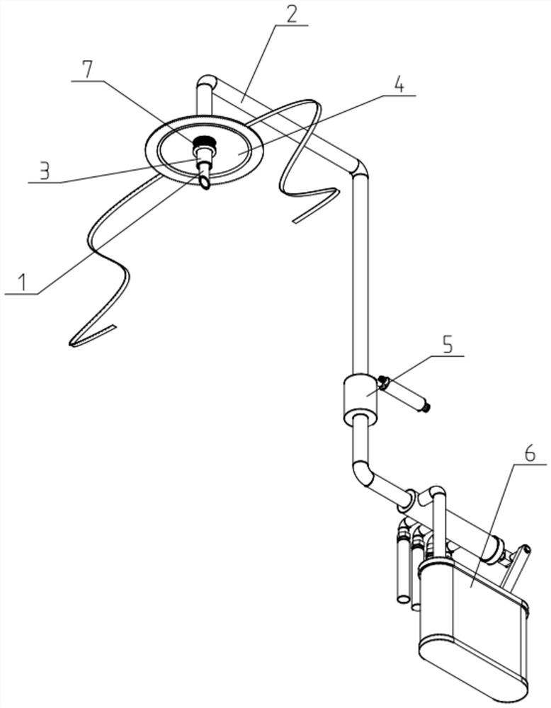
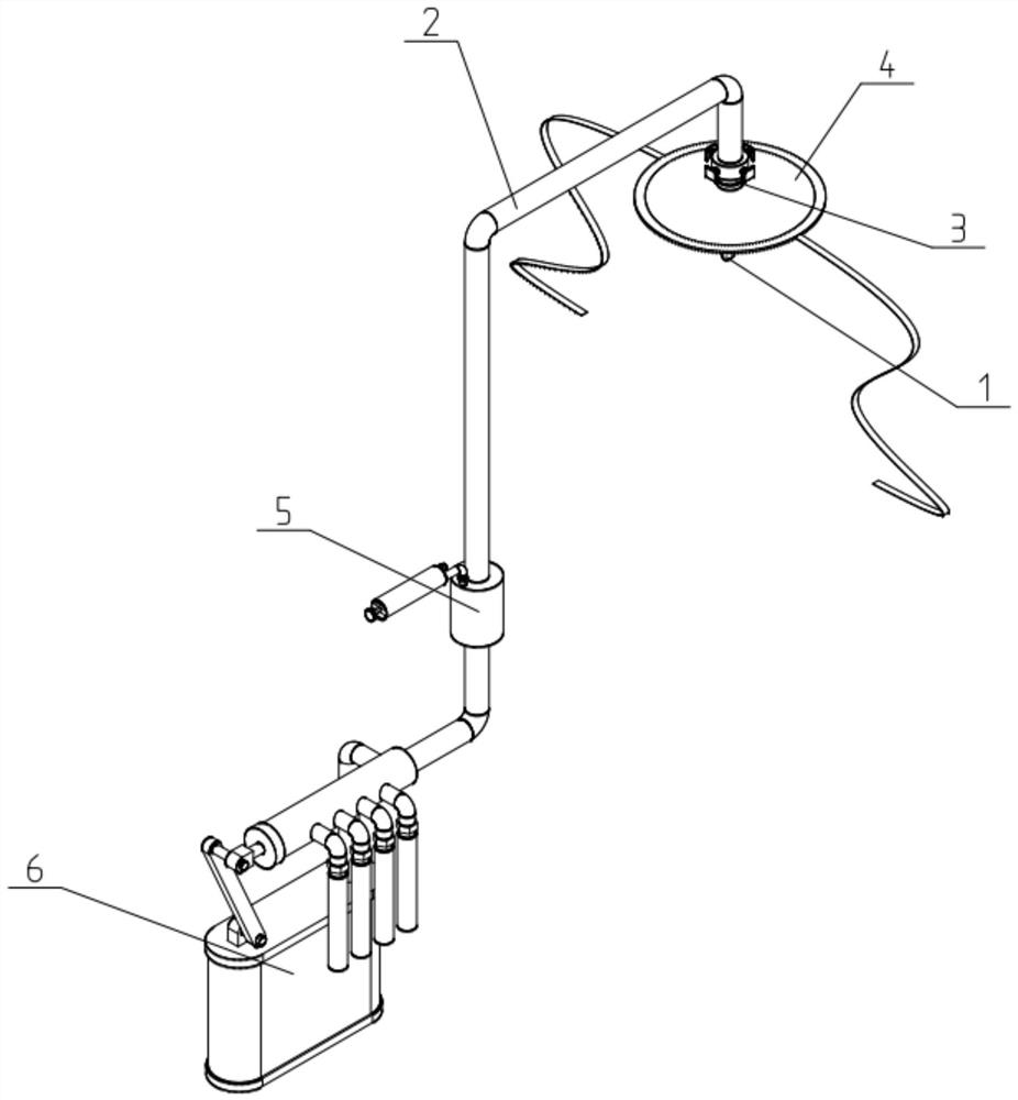
[0041] Such as Figure 1-12 As shown, a drainage collection device includes an inner drainage tube 1, an outer drainage tube 2, a plugging tube 3, an umbrella-shaped seepage collection cover 4, a negative pressure mechanism 5 and a drainage fluid collection mechanism 6; the plugging tube 3 One end of the external drainage tube 2 is fixedly connected to one end; the other end of the external drainage tube 2 is fixedly connected to and communicated with one end of the negative pressure mechanism 5; the other end of the negative pressure mechanism 5 is connected to the drainage The liquid collection mechanism 6 is fixedly connected and communicated; the inner drainage tube 1 is co-located on the inner side of the outer drainage tube 2 and the blocking tube 3, and the head end of the inner drainage tube 1 passes through to the blocking tube. The outer end of the tube 3, the seepage diversion area is formed between the inner drainage tube 1, the outer drainage tube 2 and the blocki...

specific Embodiment approach 2

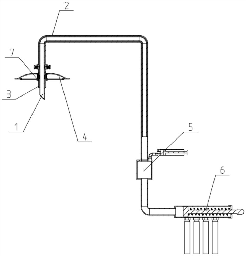
[0045] Such as Figure 1-12 As shown, the described drainage collection device also includes a blocking air bag 7; To block.

[0046] The setting of the blocking air bag 7 is used to improve the blocking effect of the blocking tube 3 on the opening of the skin and reduce the amount of seepage.

[0047] The blocking air bag 7 includes a fixed ring 701, a tension spring 702, a movable ring 703 and an inner annular air bag 704; the fixed ring 701 is fixed on the blocking tube 3, and is located in the umbrella-shaped seepage collection The inner side of the cover 4; the movable ring 703 is slidably fitted on the blocking tube 3; the movable ring 703 and the fixed ring 701 are fixedly connected by a tensioning compression spring 702, and the tensioning compression spring 702 is sleeved On the blocking tube 3; the fixed ring 701 is located between the umbrella-shaped seepage collection cover 4 and the movable ring 703; the inner annular air bag 704 is fixedly connected to the mova...

specific Embodiment approach 3

[0050] Such as Figure 1-12 As shown, the external drainage tube 2 includes a cylindrical diversion box 201, a flexible connecting pipe 202 and a limit assembly 203; the circular through holes at both ends of the cylindrical diversion box 201 are respectively connected with the plugging tube 3 and the The flexible connecting pipe 202 is sealed and fixedly connected and communicated; the flexible connecting pipe 202 is fixedly connected and communicated with one end of the negative pressure mechanism 5; the diameter of the cylindrical diversion box 201 is larger than that of the flexible connecting pipe 202 diameter and the diameter of the plugging tube 3; the side of the cylindrical diversion box 201 is uniformly surrounded by four stop components 203, and the inner sides of the four limit components 203 are press-fitted to the four sides of the inner drainage tube 1. side;

[0051] The size setting of the cylindrical diversion box 201 inside the outer drainage tube 2 can pre...


PUM


Abstract

The invention relates to the field of drainage liquid collecting equipment, in particular to a drainage collecting device which comprises an inner drainage tube, an outer drainage tube, a blocking tube, an umbrella-shaped seepage collecting cover, a negative pressure mechanism and a drainage liquid collecting mechanism. One end of the blocking tube is fixedly connected with one end of the outer drainage tube; the other end of the outer drainage tube is fixedly connected and communicates with one end of the negative pressure mechanism; the other end of the negative pressure mechanism is fixedly connected and communicates with the drainage liquid collecting mechanism; and the inner drainage tube is arranged on the inner side of the outer drainage tube and the inner side of the blocking tube in a matched mode, the head end of the inner drainage tube penetrates out to the outer end of the blocking tube, and a seepage flow guide area is formed among the inner drainage tube, the outer drainage tube and the blocking tube. The blocking tube is arranged in the device and can block an operation opening, the seepage amount is reduced, and the blocking tube is matched with the umbrella-shaped seepage collecting cover so that seepage which is not completely blocked by the blocking tube and flows out can be limited within a certain range.

Description

technical field [0001] The invention relates to the field of drainage fluid collection equipment, more specifically, to a drainage collection device. Background technique [0002] For patients after thoracic and abdominal surgery, drainage tubes and drainage bags (or drainage balls) usually need to be indwelled. In order to deal with the exudate between the stoma and the drainage tube, the current method is mainly to pad gauze in the gap between the stoma and the drainage tube to absorb the exudate, but this method has the following problems: the gauze needs to be replaced frequently , Increase the workload and cost of nursing care, and the long-term soaking of the exudate will irritate the skin around the drainage tube, which may easily cause stoma infection. Contents of the invention [0003] The purpose of the present invention is to provide a drainage collection device, which can effectively solve the problems in the prior art. [0004] In order to achieve the above ...

Claims


Application Information

Patent Timeline
Patent Type & Authority Applications(China)
IPC IPC(8): A61M1/00A61B10/00
CPCA61B10/0045
Inventor 李银玲郑学风王红申秋霞张雪杜晓妍尹晓颖麻宁魏彦华万敏敏
Owner THE AFFILIATED HOSPITAL OF QINGDAO UNIV
Why Eureka
Try Eureka