Combined forging die

A combination and mold technology, applied in the direction of manufacturing tools, forging/pressing/hammer devices, forging/pressing/hammering machinery, etc., can solve the problems of parts molding quality decline, mold damage, misalignment extrusion, etc.

Inactive Publication Date: 2021-06-11
浙江兔耀网络科技有限公司
View PDF0 Cites 0 Cited by
  • Summary
  • Abstract
  • Description
  • Claims
  • Application Information

AI Technical Summary

Problems solved by technology

[0003] When processing parts, the mold is forged by closing and closing the upper and lower molds. During the forming process, since the convex and concave parts inside the upper and lower molds do not exactly correspond exactly, the staff needs to check and adjust them, otherwise it will cause extrusion The convex and concave parts o

Method used


Image

  • Combined forging die
  • Combined forging die
  • Combined forging die

Examples


Embodiment 1

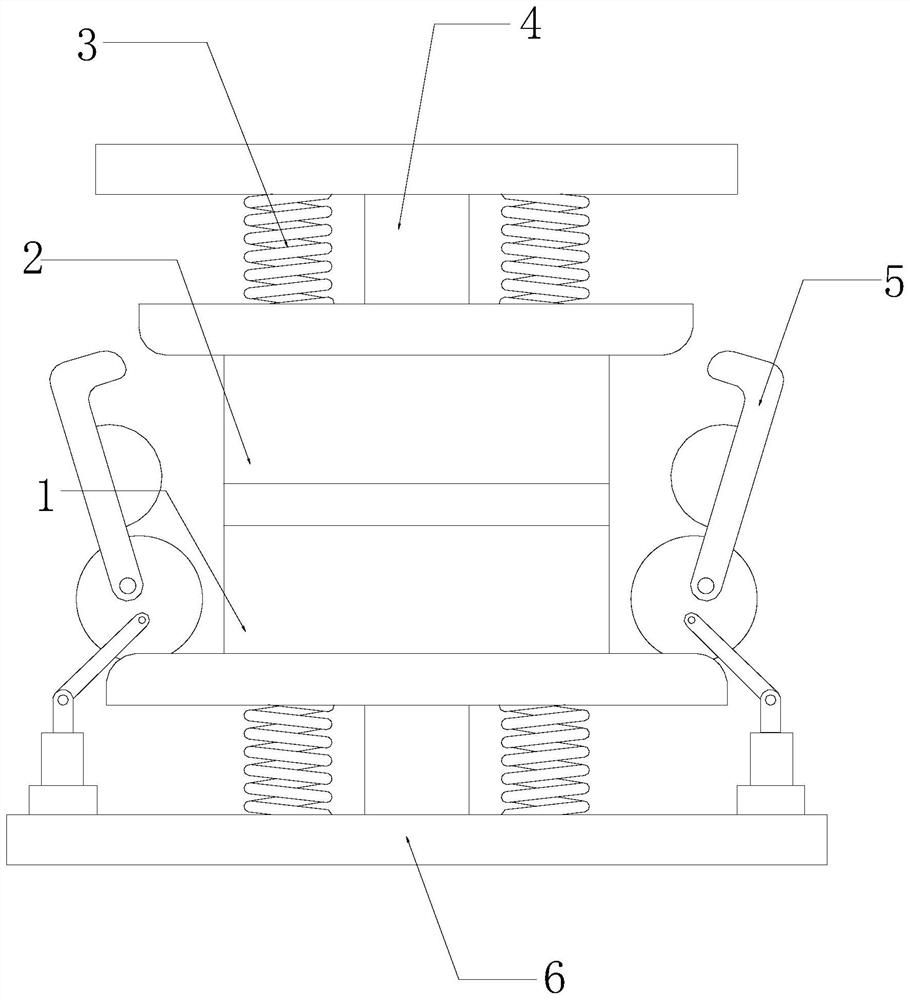
[0031] see figure 1 , the present invention provides a technical solution: a combined forging die, the structure of which includes a lower die 1, an upper die 2, a protective spring 3, an extrusion plate 4, a positioning device 5, and a base 6, and the lower die 1 is provided with There is a matching upper die 2, and the end of the upper die 2 away from the lower die 1 is provided with two protective springs 3, and the two protective springs 3 are fixedly connected with the extrusion plate 4, and the extrusion plate 4 is connected to the upper mold 2 through the protective spring 3, and the positioning device 5 engaged with it is provided on both sides of the upper mold 2, and the end of the positioning device 5 far away from the upper mold 2 is connected to the base 6, and the The base 6 is provided with two protective springs 3 , the end of the protective spring 3 far away from the base 6 is in contact with the bottom of the lower mold 1 , and both sides of the lower mold 1...

Embodiment 2

[0042] see figure 1 , the present invention provides a technical solution: a combined forging die, the structure of which includes a lower die 1, an upper die 2, a protective spring 3, an extrusion plate 4, a positioning device 5, and a base 6, and the lower die 1 is provided with There is a matching upper die 2, and the end of the upper die 2 away from the lower die 1 is provided with two protective springs 3, and the two protective springs 3 are fixedly connected with the extrusion plate 4, and the extrusion plate 4 is connected to the upper mold 2 through the protective spring 3, and the positioning device 5 engaged with it is provided on both sides of the upper mold 2, and the end of the positioning device 5 far away from the upper mold 2 is connected to the base 6, and the The base 6 is provided with two protective springs 3 , the end of the protective spring 3 far away from the base 6 is in contact with the bottom of the lower mold 1 , and both sides of the lower mold 1...


PUM


Abstract

The invention discloses a combined forging die. The combined forging die structurally comprises a lower die body, an upper die body, protection springs, an extrusion plate, positioning devices and a base. During use of the combined forging die, an adjusted chuck is blocked through cooperation of friction plates and auxiliary friction plates, so that a supporting rod can be adjusted to be in a certain balance state, the supporting rod can stably support the lower die body and the upper die body, and a die core between the upper die body and the lower die body is prevented from rotating; and then the lower die body and the upper die body are pushed and pressed through cooperation of adsorption pieces and protection pieces, so that the lower die body and the upper die body can be buckled together in parallel, it is guaranteed that convex and concave positions in the lower die body and the upper die body can be matched and correspond with each other, it is guaranteed that a blank of the die cannot be dislocated in the forming process, and the forming quality and forming efficiency of parts are improved.

Description

technical field [0001] The invention relates to the field of dies, in particular to a combined forging die. Background technique [0002] Mold, various molds and tools used in industrial production for injection molding, blow molding, extrusion, die-casting or forging forming, smelting, stamping and other methods to obtain the required products. Put it into the mold, close the mold and form it. The structure and mechanical properties of the forging mold are better than that of the casting mold. The mold is positioned by the positioning element. When processing the parts, the areas that need to be improved: [0003] When processing parts, the mold is forged by closing and closing the upper and lower molds. During the forming process, since the convex and concave parts inside the upper and lower molds do not exactly correspond exactly, the staff needs to check and adjust them, otherwise it will cause extrusion The convex and concave parts of the parts that come out are mispla...

Claims


Application Information

Patent Timeline
IPC IPC(8): B21J13/02
CPCB21J13/02B21J13/025
Inventor 张斌
Owner 浙江兔耀网络科技有限公司
Why Eureka
Try Eureka