
Motor integrated motor protection device

A technology of motor protection and protective cover, which is applied in the direction of electromechanical devices, electrical components, electric components, etc., can solve the problems of affecting the protection effect of the protective cover on the integrated motor and the wear of the contact position.

Active Publication Date: 2022-06-03
HUNAN INST OF TECH
View PDF6 Cites 0 Cited by
  • Summary
  • Abstract
  • Description
  • Claims
  • Application Information

AI Technical Summary

Problems solved by technology

[0003] When protecting the integrated motor, under normal circumstances, use two clamping parts to connect the two feet at the bottom of the integrated motor, so that the integrated motor can be stably installed in the middle of the base, and improve the stability of the integrated motor during operation. Stability, when the protective cover is placed outside the integrated motor, it can effectively protect the integrated motor. When the integrated motor is running, because the feet and the clamping parts are matched together, because the integrated motor is in the During the operation, there will be obvious jitter resonance phenomenon, and the support feet will collide with the inside of the clamping part driven by the integrated motor, and the clamping part will be enlarged accordingly due to the collision force of the support feet, and will be held by the large support The components are not enough to restrict the feet in it, so that during the operation of the integrated motor, the resonance force generated by it will shift to one side and collide with the inner wall of the protective cover, and the contact position between the two will be due to Abrasion occurs due to collision force, which affects the protective effect of the protective cover on the integrated motor

Method used


Image

  • Motor integrated motor protection device
  • Motor integrated motor protection device
  • Motor integrated motor protection device

Examples


Embodiment 1

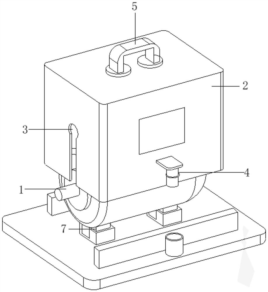
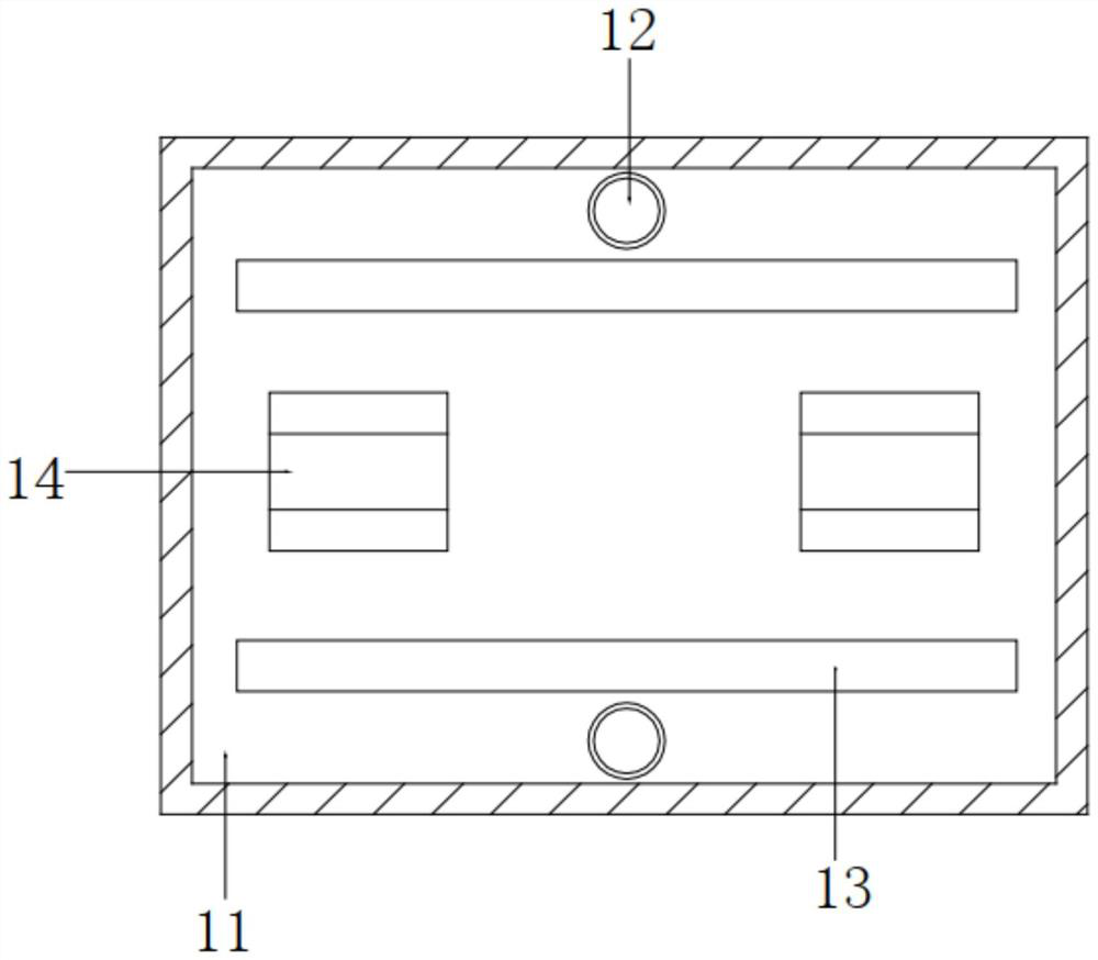
[0031] like Figure 1-2 As shown, this embodiment includes a base 11 , an integrated motor 1 disposed on the base 11 , and a protective cover 2 sleeved on the integrated motor 1 , wherein the bottom of the integrated motor 1 is provided with feet 7 , and the base 11 is There is a clamping assembly 14 that matches the support feet 7; both sides of the protective cover 2 are provided with plug connectors 4, and the base 11 is provided with a butt pipe 12 that matches the plug connectors 4; and the base 11 is also provided with The protective cover 2 has a matching limit card track 13 at the bottom; both ends of the protective cover 2 are provided with a docking slideway 3 that matches the output shaft of the integrated motor 1; and the top of the protective cover 2 is provided with a handle 5, Therefore, after the clamping assembly 14 is fixedly connected with the support feet 7, the integrated motor 1 can be stably installed on the base 11, and then the protective cover 2 is ve...

Embodiment 2

[0037] like Figure 1-2 As shown, this embodiment includes a base 11 , an integrated motor 1 disposed on the base 11 , and a protective cover 2 sleeved on the integrated motor 1 , wherein the bottom of the integrated motor 1 is provided with feet 7 , and the base 11 is There is a clamping assembly 14 that matches the support feet 7; both sides of the protective cover 2 are provided with plug connectors 4, and the base 11 is provided with a butt pipe 12 that matches the plug connectors 4; and the base 11 is also provided with The protective cover 2 has a matching limit card track 13 at the bottom; both ends of the protective cover 2 are provided with a docking slideway 3 that matches the output shaft of the integrated motor 1; and the top of the protective cover 2 is provided with a handle 5, Therefore, after the clamping assembly 14 is fixedly connected with the support feet 7, the integrated motor 1 can be stably installed on the base 11, and then the protective cover 2 is ve...


PUM


Abstract

A motor integrated motor protection device comprises a base, an integrated motor arranged on the base and a protection cover arranged on the integrated motor in a sleeving mode, supporting legs are arranged at the bottom of the integrated motor, and clamping assemblies matched with the supporting legs are arranged on the base; the two sides of the protective cover are both provided with connecting plugs, and the base is provided with butt joint pipes matched with the connecting plugs. The base is further provided with a limiting clamping channel matched with the bottom of the protection cover. When the integrated motor is used, the clamping assembly is fixedly connected with the supporting legs, so that the integrated motor can be stably installed on the base, the integrated motor is vertically covered with the protection cover, the lower end of the protection cover is connected with the limiting clamping channel, butt joint pipes on the two sides of the protection cover are inserted into the butt joint pipes, and the position of the protection cover is effectively limited; and the protection cover can stably cover the outside of the integrated motor for protection.

Description

technical field [0001] The invention relates to the technical field of motor protection, in particular to a protection device for an electromechanical integrated motor. Background technique [0002] With the continuous development of science and technology, mechatronics technology has achieved unprecedented development, and mechatronics technology has also been widely used in people's lives, and the most important thing in mechatronics is the motor. An electromagnetic device that realizes the conversion or transfer of electrical energy. Its main function is to convert mechanical energy into electrical energy. Motors are very common in industrial production and also play a vital role. When protecting mechatronic motors, Areas for improvement: [0003] When protecting the integrated motor, under normal circumstances, two brackets are used to connect the two supporting feet at the bottom of the integrated motor, so that the integrated motor can be stably installed in the middl...

Claims


Application Information

Patent Timeline
Patent Type & Authority Applications(China)
IPC IPC(8): H02K5/04H02K5/24
CPCH02K5/04H02K5/24
Inventor 隆文革邓彬李庆芬
Owner HUNAN INST OF TECH
Learn More