Hardware part surface polishing machining equipment

A technology of surface polishing and processing equipment, applied in metal processing equipment, grinding/polishing equipment, machine tools with surface polishing, etc., can solve the problem of surface polishing of the inner wall of the hole that cannot be used for hardware parts, and achieve the effect of convenient and direct cleaning

Inactive Publication Date: 2021-06-11
上海曰茶贸易有限公司
View PDF0 Cites 3 Cited by
  • Summary
  • Abstract
  • Description
  • Claims
  • Application Information

AI Technical Summary

Problems solved by technology

[0003] Since some hardware parts have holes in themselves, and the inner wall of the rotating cylinder of the hardware parts surface polishing machine can only polish the outer surface of the hardware parts, if it is necessary to polish the inner wall surface of the hole of the hardware parts, the rotating cylinder cannot Realize the situation of polishing the surface of the inner wall of the hole of the hardware part

Method used


Image

  • Hardware part surface polishing machining equipment
  • Hardware part surface polishing machining equipment
  • Hardware part surface polishing machining equipment

Examples


Embodiment 1

[0026] For example figure 1 -example Figure 5 Shown:

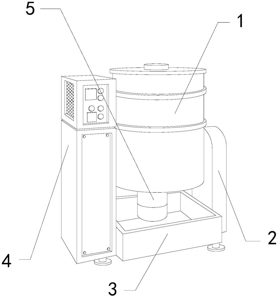
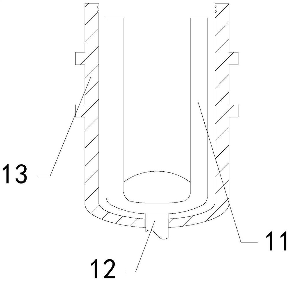
[0027] The invention provides a surface polishing processing equipment for hardware parts, the structure of which includes a grinding cylinder 1, a side fixing plate 2, a bottom plate 3, a control electric box 4, and a driver 5. The side fixing plate 2 is welded to the right side of the bottom plate 3, The control electrical box 4 is installed on the left side of the bottom plate 3, the driver 5 is connected to the bottom of the grinding cylinder 1, and the grinding cylinder 1 is fixed between the inner side of the side fixing plate 2 and the inner side of the control electrical box 4 The grinding cylinder 1 includes a rotating cylinder 11 , a rotating shaft 12 , and an outer frame 13 , the rotating cylinder 11 is fixed on the upper end of the rotating shaft 12 , and the rotating shaft 12 penetrates the inner position of the outer frame 13 .

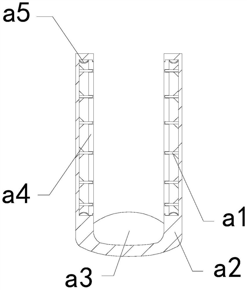
[0028] Wherein, the rotating cylinder 11 includes an outreaching rod a1, a fr...

Embodiment 2

[0034] For example Image 6 -example Figure 8 Shown:

[0035] Wherein, the inner solid plate a3 includes a clearing mechanism c1, an embedding cavity c2, and a plate surface c3, the clearing mechanism c1 is fixed in the inner position of the embedding cavity c2, and the embedding cavity c2 is embedded in the inner position of the plate surface c3, so There are four embedding cavities c2, two of which are evenly distributed symmetrically inside the board surface c3, through which the debris generated by grinding of hardware parts can be collected.

[0036]Wherein, the cleaning mechanism c1 includes a collection block c11, an outer contact surface c12, an anchor block c13, and a bottoming block c14. The collection block c11 is fixed on the upper surface of the outer contact surface c12, and the outer contact surface c12 The bottom is attached to the upper surface of the retaining block c13, the retaining block c13 is embedded in the inner position of the bottoming block c14, ...


PUM


Abstract

The invention discloses hardware part surface polishing machining equipment which structurally comprises a polishing cylinder, a side fixing plate, a bottom plate, a control electric box and a driver, the side fixing plate is welded to the right side of the bottom plate, the control electric box is installed on the left side of the bottom plate, and the driver is connected with the bottom of the polishing cylinder; and the polishing cylinder is fixed between the inner side of the side fixing plate and the inner side of the control electric box, a hardware part extrudes an extruded plate, the extruded plate can contract inwards along a frame, and therefore an outwards-extending rod can extend outwards till the outwards-extending rod can extend into a hole of the hardware part, so that a rotating rod can drive the polishing surface to polish the inner wall of the hole of the hardware part smoothly, an impact block can generate impact vibration on a suction block through suction force generated by the suction block on the impact block, and therefore hardware chippings on a collecting block and a rotating shaft can be vibrated to be loosened, and the hardware chippings in the rotating cylinder can be conveniently and directly cleaned in the follow-up process.

Description

technical field [0001] The invention relates to the field of surface polishing processing in hardware production, in particular to a surface polishing processing equipment for hardware parts. Background technique [0002] Hardware parts surface polishing machine is mainly used to polish the surface of hardware parts. By introducing a large number of hardware parts into the hardware parts surface polishing machine, and then rotating at a high speed through the rotating cylinder inside the grinding cylinder, it can make The inner wall of the rotating cylinder polishes the surface of hardware parts, which is a common equipment in the hardware parts production industry. Based on the above description, the inventors found that the existing hardware parts surface polishing processing equipment mainly has the following deficiencies, for example: [0003] Since some hardware parts have holes themselves, and the inner wall of the rotating cylinder of the hardware parts surface polish...

Claims


Application Information

Patent Timeline
Patent Type & Authority Applications(China)
IPC IPC(8): B24B27/00B24B31/02B24B31/12B24B5/48B24B55/06
CPCB24B5/48B24B27/0076B24B31/02B24B31/12B24B55/06
Inventor 王辉
Owner 上海曰茶贸易有限公司
Why Eureka
Try Eureka