
A transmission shaft heat-insulated power transfer device for an electric vehicle

A technology for power transfer and electric vehicles, which is applied to transmission parts, control devices, vehicle components, etc., and can solve problems such as poor heat dissipation

Active Publication Date: 2021-09-10
范小龙
View PDF5 Cites 0 Cited by
  • Summary
  • Abstract
  • Description
  • Claims
  • Application Information

AI Technical Summary

Problems solved by technology

[0009] The purpose of the present invention is to provide a transmission shaft heat-insulated power transfer device for electric vehicles to solve the problem of poor heat dissipation in the background technology mentioned above

Method used


Image

  • A transmission shaft heat-insulated power transfer device for an electric vehicle
  • A transmission shaft heat-insulated power transfer device for an electric vehicle
  • A transmission shaft heat-insulated power transfer device for an electric vehicle

Examples


Embodiment 1

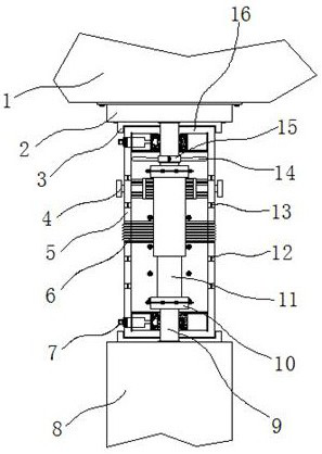
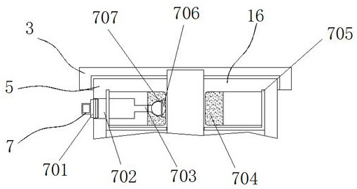
[0035] Example 1: See Figure 1-6 , a transmission shaft heat-insulated power conversion device for electric vehicles, including an engine 1, a left casing 5, a generator 8 and a right casing 16, the bottom end of the engine 1 is provided with a generator 8, and the bottom of the engine 1 The model can be 6105, the model of generator 8 can be EM390, the bottom end of engine 1 is fixedly connected with flywheel group 2, the bottom end of flywheel group 2 and the top of generator 8 are respectively fixedly connected with movable groove 3, and movable groove 3 One side between the inside is provided with a left housing 5, the other side between the inside of the movable groove 3 is provided with a right housing 16, and the two ends between the right housing 16 and one side of the left housing 5 are respectively provided with three The group engaging structure 17, the output ends of the engine 1 and the generator 8 are respectively fixedly connected with an output rod 9, and a tra...

Embodiment 2

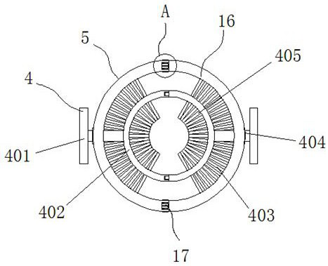
[0040] Embodiment 2: The cleaning structure 4 is composed of a pull rod 401, a fixed rod 402, a first hair brush 403, a chute 404 and a second hair brush 405, and the chute 404 is respectively arranged on the side of the left housing 5 and the right housing 16 Inside, the inside of the chute 404 is provided with a pull rod 401, and one side of the pull rod 401 is fixedly connected with a fixed rod 402, one side of the fixed rod 402 is fixedly connected with a first brush 403, and the other side of the fixed rod 402 is fixedly connected with a Second hair brush 405;

[0041] The first hairbrush 403 and the second hairbrush 405 are in the same horizontal plane;

[0042] Specifically, such as figure 1 and figure 2 As shown, when the splicing of the left housing 5 and the right housing 16 is completed, the pull rod 401 is also spliced ​​and fixed with the fixing rod 402. After that, hold the pull rod 401 with both hands, and lift it up and down along the direction of the chute ...

Embodiment 3

[0043] Embodiment 3: Bellows 6 are respectively provided at the middle positions of the left housing 5 and the right housing 16;

[0044] Specifically, such as figure 1 and Figure 4 As shown, when the length of the transmission shaft 11 is stretched or shortened according to the installation needs of the electric vehicle, the top or bottom end of the left housing 5 and the right housing 16 can be held and pulled in this direction to achieve The extension and compression of the device are adapted to drive shafts 11 of different lengths.


PUM


Abstract

The invention discloses a transmission shaft heat-insulated power transfer device for electric vehicles, specifically relates to the technical field of transmission shaft transfer devices, including an engine, a left casing, a generator and a right casing, the bottom of the engine A generator is arranged at the end of the motor, and a flywheel set is fixedly connected to the bottom end of the engine. The bottom end of the flywheel set and the top end of the generator are respectively fixedly connected with movable slots, and a left shell is arranged on one side between the inside of the movable slots. body, and the other side between the inside of the movable tank is provided with a right housing. In the present invention, a heat dissipation structure is provided between the inner side of the left housing and the right housing. When the transmission shaft rotates itself under the drive of the generator, the fan blades fixedly connected around the outer side of the fixed block rotate accordingly, and are evenly arranged. The heat dissipation holes and gauze nets use the generated wind to dissipate heat and cool down the transmission shaft inside the device, and increase the distance between the generator and the engine, effectively blocking the mutual transfer of heat.

Description

technical field [0001] The invention relates to the technical field of transmission shaft adapters, in particular to a transmission shaft heat-insulated power adapter for electric vehicles. Background technique [0002] In the 21st century with the rapid development of science and technology, electric vehicles have been gradually used for transportation. The transmission of energy mostly depends on a transmission shaft that can rotate at high speed and connect the engine and generator. To adapt to multi-directional adjustment and extension, but the traditional power adapter lacks effective fixation and poor heat insulation effect, it is difficult to meet the current mainstream needs, so it is necessary to prepare a new type of heat-insulated power adapter to Solve these problems. [0003] In the process of realizing the present invention, the inventors have found that at least the following problems in the prior art have not been resolved: [0004] (1) The traditional tran...

Claims


Application Information

Patent Timeline
Patent Type & Authority Patents(China)
IPC IPC(8): B60K17/04F16H57/04B08B1/00F16N7/00
CPCB60K17/04F16H57/0416F16N7/00F16N2210/04B08B1/30B08B1/12
Inventor 范小龙
Owner 范小龙
Learn More