An aerial refueling device with lateral restraint hose

A technology for aerial refueling and hoses, applied in transportation and packaging, aircraft parts, etc., can solve problems such as susceptibility to airflow disturbance, docking failure, etc.

Active Publication Date: 2022-06-24
HARBIN INST OF TECH
View PDF9 Cites 0 Cited by
  • Summary
  • Abstract
  • Description
  • Claims
  • Application Information

AI Technical Summary

Problems solved by technology

[0004] The purpose of the present invention is to solve the problem that existing flexible hoses are susceptible to airflow disturbances during the docking process, resulting in docking failures, and to provide an aerial refueling device with laterally constrained hoses

Method used


Image

  • An aerial refueling device with lateral restraint hose
  • An aerial refueling device with lateral restraint hose
  • An aerial refueling device with lateral restraint hose

Examples


specific Embodiment approach 1

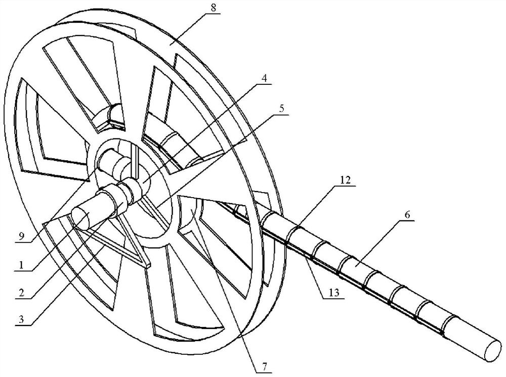
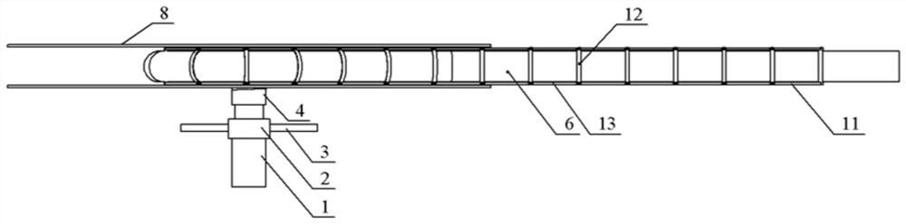
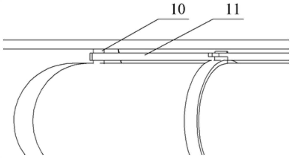
[0027] Embodiment 1: Combining Figure 1 to Figure 8 This embodiment is described. An aerial refueling device with a laterally restrained hose in this embodiment includes an oil pipeline 1, a rotary joint 2, a fixed support 3, a right-angle adapter 4, a support beam 5, a hose 6, and a winch. 7. The side plate 8, the outer frame and the fixing pin 10; the capstan 7 is a cylindrical structure, the outer cylindrical surface of the capstan 7 is provided with a guide hole 9, the capstan 7 is arranged vertically, the number of side plates 8 is two, and the two sides The plate 8 is vertically opposite to the left and right ends of the capstan 7 and is integrally connected with the capstan 7. The side plate 8 is an annular plate-like structure; The number of beams 5 is three, and the three support beams 5 are arranged between the right-angle adapter 4 and the side plate 8 in an annular array. One end of the support beam 5 is fixed to the outer wall of the right-angle adapter 4, and th...

specific Embodiment approach 2

[0028] Specific implementation mode 2: Combining Figure 4 and Figure 5 Illustrating this embodiment, the hose 6 of this embodiment includes an outer elastomer layer 14 and an inner insulator layer 16 , the outer elastomer layer 14 and the inner insulator layer 16 are both circular tubular structures, and the outer elastomer layer 14 is sleeved inside Outside of insulator layer 16 . In this way, the hose 6 is composed of the outer elastomer layer 14 and the inner insulator layer 16 , which can ensure the flexibility of the hose 6 . Other components and connection relationships are the same as in the first embodiment.

specific Embodiment approach 3

[0029] Specific implementation three: combination Figure 4 and Figure 5Describing this embodiment, the hose 6 of this embodiment further includes a steel wire reinforcement layer, which is arranged between the outer elastomer layer 14 and the inner insulator layer 16 , and the steel wire reinforcement layer includes several steel wires 15 , and the steel wires 15 extend along the hose 6 . The length direction wraps outside the inner insulator layer 16 . In this way, arranging the reinforcing layer of steel wire 15 between the outer elastomer layer 14 and the inner insulator layer 16 can increase the tensile stiffness of the hose 6 and reduce the expansion and contraction rate. Other compositions and connection relationships are the same as in the first or second embodiment.


PUM


Abstract

An aerial refueling device with lateral restraint hoses relates to the technical field of aerial refueling. The invention solves the problem that the existing flexible hoses are easily disturbed by the air flow during the docking process, resulting in the failure of the docking. The hose of the present invention is wound on the capstan before being unwound, and the first end of the hose enters the interior of the capstan through the guide hole to be bent and then connected to the other end of the right-angle adapter. The two first hinge ends on both sides of the hose and close to the end of the hose are connected by a ring, between each pair of first hinges and each adjacent pair of second hinges They are respectively connected by a circular ring, and each adjacent pair of second hinges is connected by a circular ring, and the circular ring is sleeved on the hose. While ensuring the longitudinal movement and normal retraction of the hose, the invention reduces the lateral impact of disturbance on the hose, narrows the movement range of the hose, and reduces the difficulty of docking for aerial refueling.

Description

technical field [0001] The invention relates to the technical field of aerial refueling, in particular to an aerial refueling device with a lateral restraint hose. Background technique [0002] In-flight refueling technology refers to the technology of refueling one aircraft in the air to another or several aircraft, which can greatly increase the flight range of the aircraft, prolong the air time of the aircraft, increase the payload of the aircraft, and solve the problem between the fuel load and the take-off distance. The contradiction has become an important means for the modern air force to effectively expand the combat range and combat capability of air power. The flexible aerial refueling hose is easy to retract, small in size and simple in structure, but the flexible hose is easily disturbed by airflow during the docking process, resulting in docking failure. In order to reduce the difficulty of docking and improve the success rate of docking, the invention provides...

Claims


Application Information

Patent Timeline
Patent Type & Authority Patents(China)
IPC IPC(8): B64D39/02B64D39/06
CPCB64D39/02B64D39/06
Inventor 黄意新刘海洲刘天喜杨宇张程田浩赵阳
Owner HARBIN INST OF TECH
Why Eureka
Try Eureka