

Glass cutting and breaking device
A glass cutting and breaking technology, which is applied in glass cutting devices, glass manufacturing equipment, manufacturing tools, etc., can solve the problems of lower yield rate, inability to cut glass pieces, adjust cutting knife strength, fragmentation, etc., and achieve high quality of breaking pieces , Avoid manual cutting deflection, high cutting efficiency
- Summary
- Abstract
- Description
- Claims
- Application Information
AI Technical Summary
Problems solved by technology
Method used
Image

Examples
Embodiment 1
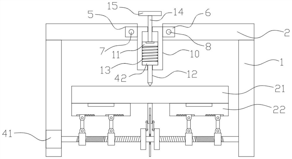
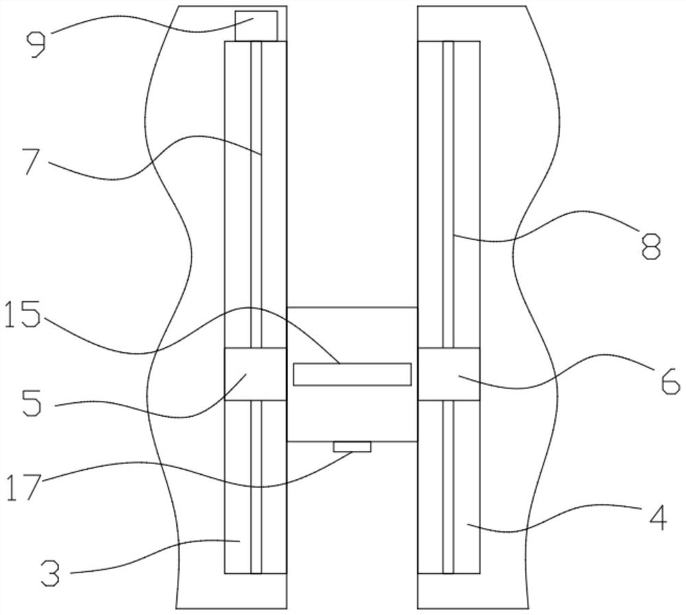
[0026] refer to Figure 1-4 , a glass cutting and breaking device, including two first vertical plates 1, the upper ends of the two first vertical plates 1 are symmetrically fixedly connected with a top plate 2, and the opposite sides of the two top plates 2 are respectively provided with a first chute 3 and a The second chute 4, the first chute 3 and the second chute 4 are slidably connected with the first slider 5 and the second slider 6 respectively, and the first slider 5 and the second slider 6 are respectively inserted with Screw mandrel 7 and guide rod 8, the first slider 5 is threadedly connected with screw mandrel 7, the inner wall of first chute 3 is embedded with the first motor 9 that is used to drive screw mandrel 7 to rotate, and the second slide block 6 and guide rod 8 is slidably connected, and the guide rod 8 is fixed on the inner walls of both sides of the second chute 4 . The movement of the moving cylinder 10 fixedly connected with the first slide block 5 ...
Embodiment 2
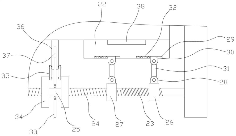
[0039] refer to Figure 5 , this embodiment makes the following improvements on the basis of Embodiment 1: a proximity switch 39 is fixedly installed on the side where the two first nut blocks 26 are close to each other, the proximity switch 39 is electrically connected with the vacuum generator, and the rotating rod 25 is at the second A ring plate 40 is fixedly sleeved between the first external thread 23 and the second external thread 24 , and the ring plate 40 can prevent the first nut block 26 from moving too long.
[0040] When the first nut block 26 moves to the sensing distance of the proximity switch 39, it indicates that the glass sheet 21 has been broken, and the vacuum generator automatically stops working without manual control, reducing work steps and improving the breaking efficiency.
PUM
 Abstract
Description
Claims
Application Information