
Duplex stacked filter

A double filter and filter technology, applied in the direction of fluid pressure actuation device, servo motor assembly, fluid pressure actuation system component, etc., can solve the problem of directional valve, flow valve, pressure control valve, valve stuck valve, hydraulic system filter The protection mechanism is incomplete, and the internal pollutants cannot be effectively purified, so as to achieve the effect of convenient installation and maintenance, avoiding solid foreign matter blocking, and easy cleaning and maintenance.

Pending Publication Date: 2021-06-11
何荣志
View PDF9 Cites 0 Cited by
  • Summary
  • Abstract
  • Description
  • Claims
  • Application Information

AI Technical Summary

Problems solved by technology

[0003] In the current hydraulic system, although a relatively complete filtration system is applied, the pump outlet (or valve table) is equipped with a high-pressure P-tube filter, and the oil tank is also installed with an oil return filter and a circulation filter, which play a role in the control valve of the hydraulic system. Good protection; however, in actual use, directional valves, flow valves and pressure control valves often get stuck, which causes great economic losses in production every year
The reason is that these three types of filters cannot effectively purify the internal pollutants produced by the hydraulic pipelines, oil cylinders, and hydraulic motors in front of the fluid valve table, so the current hydraulic system filtration protection mechanism is not complete.

Method used


Image

  • Duplex stacked filter
  • Duplex stacked filter
  • Duplex stacked filter

Examples


Embodiment Construction

[0023] The present invention will be further described in detail below with reference to the accompanying drawings embodiments.

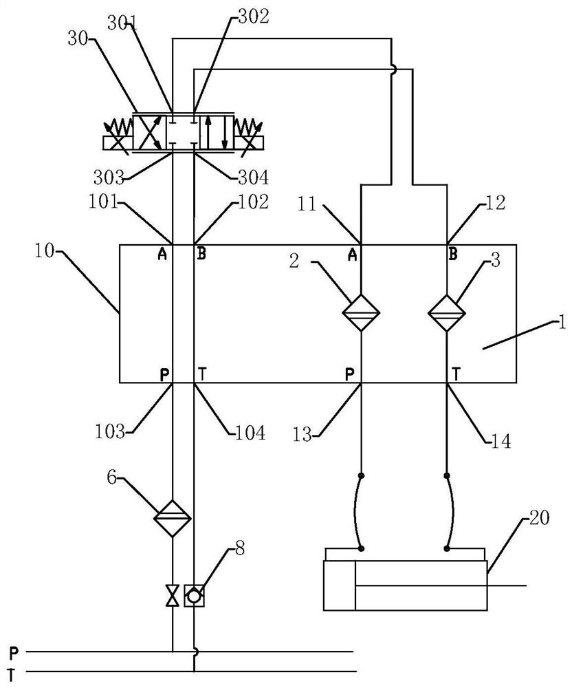
[0024] The invention is taken as an example with the cylinder 20 controlled by the most common proportional direction valve 30, and the present invention is used as an example in the hydraulic circuit as an example, and the application principle is explained.

[0025] In the filter structure according to the present invention, the filter structure corresponding to the 6-through-diameter logic control valve is an example, indicating the principle of the internal structure, and has a similar internal structure for 10 pacating diameter, 16-diameter logic control valve, is not difficult. Promote its application.

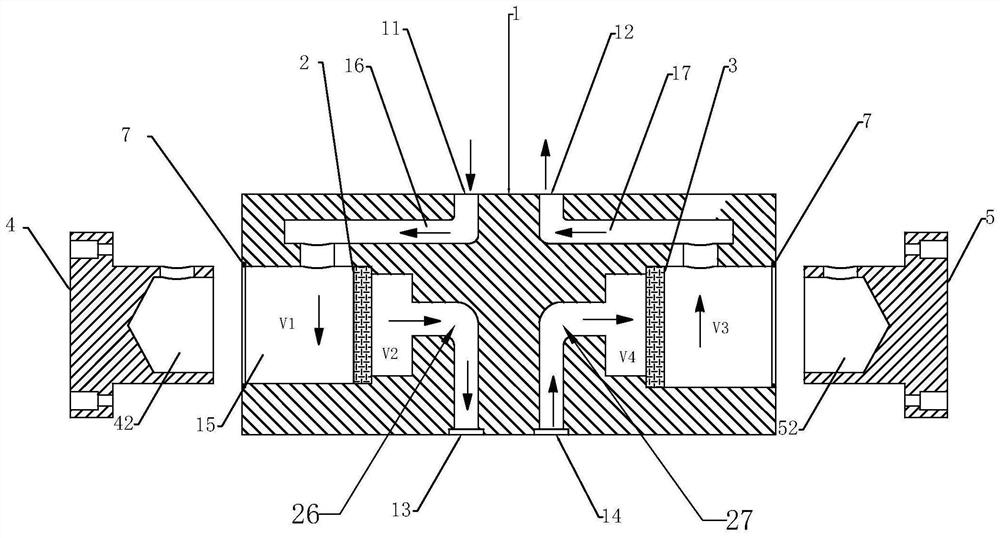
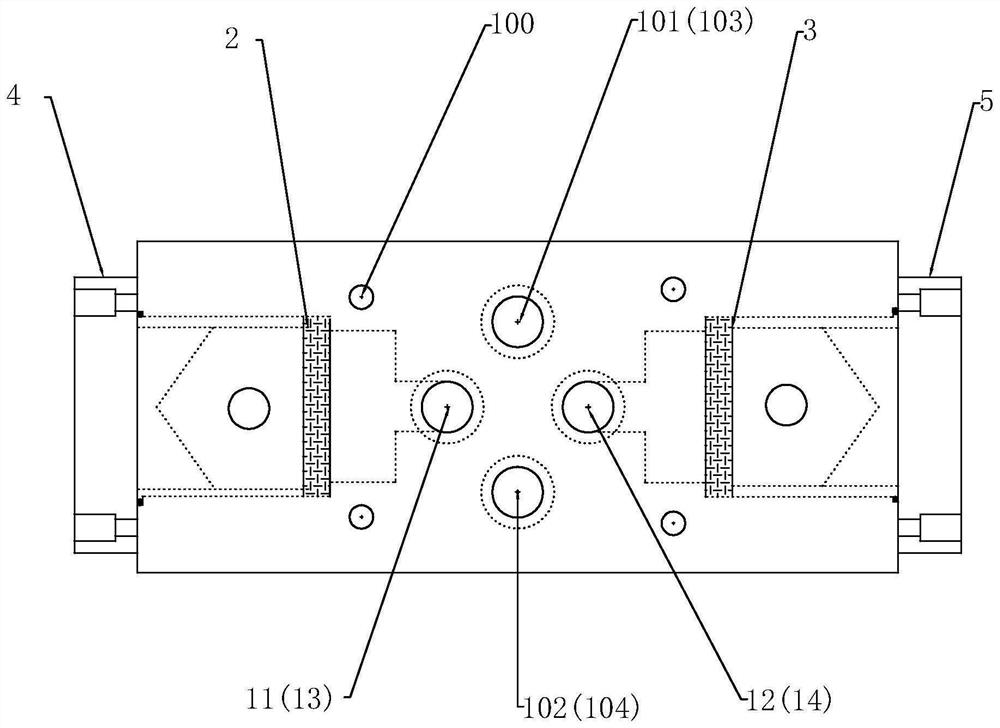
[0026] Such as Figure 1 ~ 6 As shown, a two-laminate filter includes a piece of valve block 1, two sets of filter cartridges 2 and 3 and two valve sleeves 4 and 5; the filter is superimposed in a valve block 1. The primary layer is mounted on the ...


PUM

PropertyMeasurementUnit
Circle radiusaaaaaaaaaa

Abstract

The invention discloses a duplex stacked filter which is characterized by comprising a valve block, two filter elements and two valve sleeves; the filter is installed on a hydraulic valve stand in a mode that the valve block is connected in a stacked mode, the filter is located on the bottommost layer of a hydraulic control valve, at least four standard control oil ways P, T, A and B of a hydraulic logic valve are arranged in the valve block, and the filter elements are detachably arranged in the positions, located on control oil ways A and B, of the interior of the valve block; and the valve sleeves for positioning and fixing the filter elements are detachably mounted on the two sides of the valve block. The duplex stacked filter is simple and reasonable in structure, small in size and convenient to install and maintain, the situation that the hydraulic valve breaks down due to blocking of solid foreign matter generated in a hydraulic execution element and a pipeline of the hydraulic execution element is effectively avoided, the blank that an oil way A and an oil way B are difficult to purify in the past is filled, and meanwhile, the filter elements can be conveniently detached and are convenient to clean and maintain.

Description

Technical field [0001] The present invention belongs to the technical field of hydraulic system, and is relate to a hydraulic filter, and more particularly to a double laminate filter. Background technique [0002] In modern industries, a large amount of hydraulic system is applied on various machine production lines, and the reliability of hydraulic system is extremely important. The caval valve failure generated by the hydraulic system has brought huge economic losses. [0003] In the current hydraulic system, although a relatively complete filtering system is applied, the pump exit (or valve block) is equipped with a high pressure P tube filter, and the oil box is also installed, and the hydraulic system control valve has been installed. Good protection; but in actual use, the direction of directional valves, flow valves and pressure control valve valves often occur, which have a large production economic loss every year. The reason is because the three filters currently do no...

Claims


Application Information

Patent Timeline
IPC IPC(8): F15B21/041F15B13/04
CPCF15B21/041F15B13/0401
Inventor 何荣志
Owner 何荣志
Learn More