Hinge

A hinge and hinge shaft technology, applied in the field of hinges, can solve the problem that the hinge cannot connect to electric circuits or waterways, and achieve the effects of improving aesthetics, improving service life, and reducing accidental damage

Pending Publication Date: 2021-06-11
上海轲吉智能科技有限公司 +1
View PDF0 Cites 0 Cited by
  • Summary
  • Abstract
  • Description
  • Claims
  • Application Information

AI Technical Summary

Problems solved by technology

[0003] The technical problem to be solved by the present invention is to provide a hinged

Method used


Image

  • Hinge
  • Hinge
  • Hinge

Examples


Embodiment 1

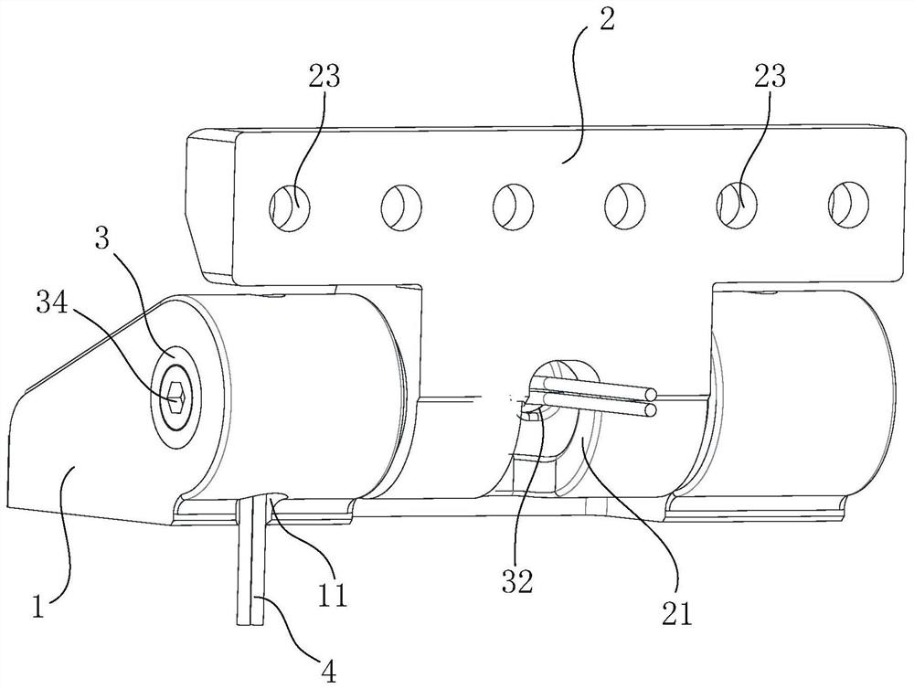
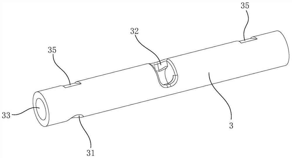
[0060] Such as Figure 1 to 3 The hinge of the first embodiment of the present invention is shown, the hinge includes a hinge shaft 3, and a first hinge 1 and a second hinge 2 that are set therein, and the two hinges can be relatively rotated. A plurality of mounting holes 23 are provided on both hinges for mounting hinges on other components. The hinge shaft has a hollow chamber 33, and the hinge shaft is opened with two hinge shaft holes in communication with the hollow cavity 33, and the hinge is opened, and the hinge shaft hole is corresponding to the communication hole, and the corresponding hinge shaft hole and communication The hole is connected.

[0061] By this arrangement, the electric wire 4 can penetrate from a set of communication holes and hinge shaft holes 22, and then wear from another set of hinge shaft holes 22 and communication holes to achieve communication, thereby making two pass The wires 4 between the hinged members can be concealed, and it is not naked to i...

Embodiment 2

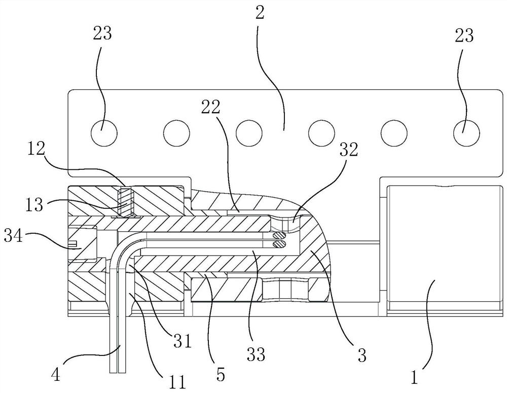
[0070] Such as Figure 4 with Figure 5 The present embodiment is shown in the first embodiment of the present invention, and the hinge in the present embodiment can be shown in the present embodiment. Specifically, the hinge shaft is provided with a sealing ring 6 (e.g., the sealing ring 6 can be a oil seal), and the sealing ring 6 is sealed between the sealing ring 6 and the hinge shadow, and the sealing ring 6 is sealed between the sealing ring 6 and the shaft hole 22. Set, the two sealing ring 6, the hinge shaft is circularly surrounded by a ring-shaped receiving chamber 9, and the second communication hole 21 and the second hinge shaft hole 22 communicate with the receiving chamber 9, the fluid may sequentially pass through the first communication hole 11. In the case where the first hinge shaft hole 31 flows into the cavity 33, the fluid flows from the second hinge shaft hole 32 into the housing chamber 9, and finally flows from the receiving chamber 9 from the second communic...


PUM


Abstract

The invention discloses a hinge. The hinge comprises a hinge shaft and two hinge bodies, the hinge shaft is sleeved with the two hinge bodies so that the two hinge bodies can rotate relatively, the hinge shaft is provided with a hollow cavity, the hinge shaft is provided with two hinge shaft holes communicating with the hollow cavity, the hinge bodies are provided with two communicating holes, the hinge shaft holes are in one-to-one correspondence with the communicating holes, and the corresponding hinge shaft hole and communicating hole are in communication with each other. A line or a pipeline can penetrate through the communicating holes, the hinge shaft holes and the hollow cavity, or the hollow cavity serves as a part of the pipeline to achieve communication of the pipeline, so that the line and the pipeline between two parts connected through the hinge are arranged in a hidden mode and cannot be exposed outside, the parts are prevented from damaging the line or the pipeline in the rotating process, accidental damage to the line and the pipeline in the transportation process and operation and maintenance is reduced, the service life can be prolonged, and the appearance of equipment is neat.

Description

Technical field [0001] The present invention relates to a hinge. Background technique [0002] In a medical device, a large number of rotational opening and cubic components are applied, which are typically supported and connected by hinges. With the development of medical device technology and the diversity of medical equipment varieties, the lines and pipes used in the medical device for energization and water are increasingly complex, and the hinges in the prior art do not have functions of communication lines or lines. Therefore, the lines and lines connected between relative rotating components are directly exposed directly, affect the appearance of the equipment, and there is a hidden danger of the line and the pipeline being accidentally damaged. Inventive content [0003] The technical problem to be solved by the present invention is to overcome the deficiencies that the hinges in the prior art cannot connect the circuit or water paths, and provide a hinge. [0004] The ...

Claims


Application Information

Patent Timeline
Patent Type & Authority Applications(China)
IPC IPC(8): F16C11/04F16C11/10F16L27/093H02G11/00
CPCF16C11/04F16C11/103F16L27/0849F16L27/093H02G11/00
Inventor 孙业勤孙珺鲍洪涛王龙郭勇梅挥宙
Owner 上海轲吉智能科技有限公司
Why Eureka
Try Eureka