
Conveniently used mechanical sealing element

A technology for mechanical seals and plastic parts, which is applied in the direction of mechanical equipment, passing components, pipes/pipe joints/pipe fittings, etc., which can solve the problems of difficult installation and disassembly of pipe seals, and achieve simple structure, convenient use, and good sealing effect Effect

Inactive Publication Date: 2021-06-11
西安格莱特精密机械有限公司
View PDF0 Cites 1 Cited by
  • Summary
  • Abstract
  • Description
  • Claims
  • Application Information

AI Technical Summary

Problems solved by technology

[0004] The invention provides an easy-to-use mechanical seal, which solves the problem that the current pipeline seal is not easy to install and disassemble

Method used


Image

  • Conveniently used mechanical sealing element
  • Conveniently used mechanical sealing element
  • Conveniently used mechanical sealing element

Examples


Embodiment 1

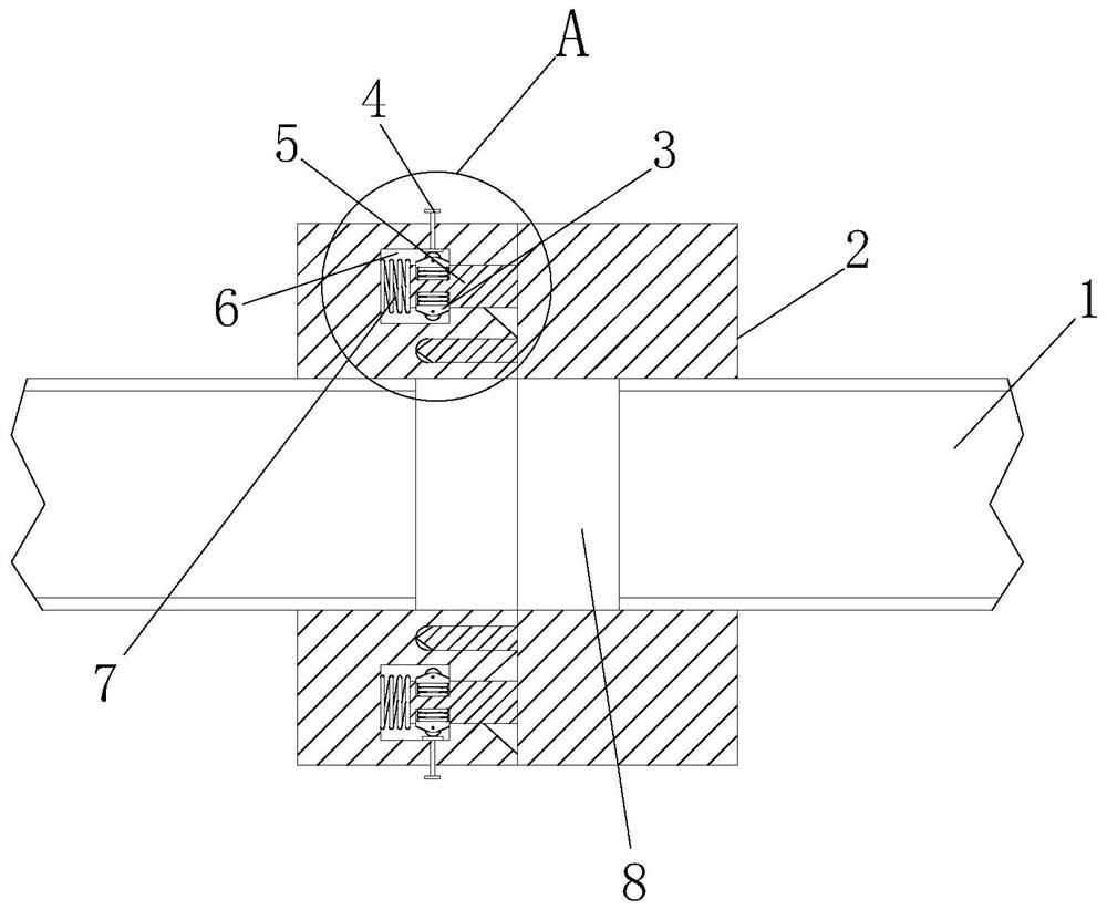
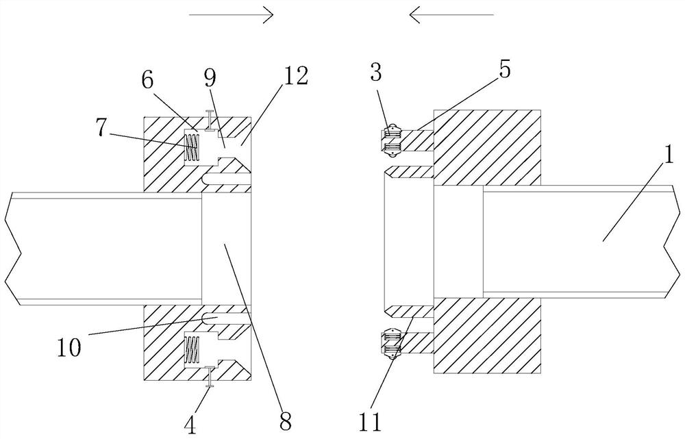
[0020] see Figure 1-3 , the present invention provides an easy-to-use mechanical seal, which includes a pipe 1 and two attached discs 2, and the two discs 2 are provided with threads that run through the two ends of the disc 2 and are screwed with the pipe 1 respectively. Hole 8, the opposite side on one of the discs 2 is fixedly installed with a ring-shaped plastic part 11, and the other disc 2 is provided with a circular card slot 10 that is compatible with the ring-shaped plastic part 11, and the two discs 2 A latch 5 is fixedly installed on the opposite side of one, and a slot 9 compatible with the latch 5 is provided on the other disk 2, and the bottom of the slot 9 communicates with a rectangular slot 6, and the diameter of the rectangular slot 6 is larger than The diameter of the slot 9, the bolt 5 is provided with an elastic expansion member 3 that is compatible with the rectangular slot 6, and the disc 2 is provided with a reset mechanism that resets the elastic expa...

Embodiment 2

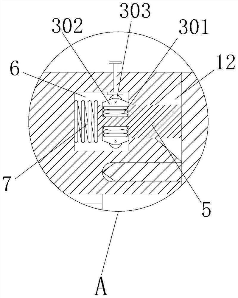
[0023] see Figure 1-3 , the present embodiment is further optimized on the basis of embodiment 1, specifically, the disk 2 that has the slot 9 is located on the opposite side and has a chute 12, and the bottom of the chute 12 is in contact with the slot 9. Connected, the elastic expansion part 3 includes a spring groove provided on the latch 5, the bottom of the spring groove is fixedly equipped with a second spring 301, and the top of the second spring 301 is fixedly installed with a limit block 302, and the limit block 302 is far away from the second spring. One side of 301 is hinged with roller 303 .

[0024] In this embodiment, the bottom of the inner wall of the rectangular slot 6 is fixed with the first spring 7 , and both sides of the limit block 302 on the roller 303 are set as slopes.

[0025] The reset mechanism includes a through hole provided on the disk 2 and positioned on one side of the elastic expansion member 3, and a push rod 4 is inserted through the throu...


PUM


Abstract

The invention provides a conveniently used mechanical sealing element. The conveniently used mechanical sealing element comprises a pipeline and two attached discs, wherein threaded holes which penetrate through two end surfaces of the discs and are screwed with the pipeline are formed in the two discs, annular plastic pieces are fixedly installed on the opposite sides of one disc, and round clamping grooves matched with the annular plastic pieces are formed in the other disc. A plug pin is fixedly installed on the opposite side of one of the two discs, a slot matched with the plug pin is formed in the other disc, the bottom of the slot is communicated with a rectangular clamping groove, the aperture of the rectangular clamping groove is larger than that of the slot, and an elastic telescopic piece matched with the rectangular clamping groove is arranged on the plug pin. As the pipeline is screwed in the threaded hole in the disc, the plug pin is inserted into the slot, and the aperture of the rectangular clamping groove is larger than that of the slot, the elastic telescopic piece can be clamped in the rectangular clamping groove.

Description

technical field [0001] The invention relates to the technical field of pipeline sealing equipment, in particular to an easy-to-use mechanical seal. Background technique [0002] Pipe-pipe connection The connection method between pipes, pipe joints, valves and inlet and outlet pipes on the equipment is determined by the nature of the fluid, pressure and temperature, as well as the material, size and installation place of the pipes. There are mainly threaded connections, method There are four methods of flange connection, socket connection and welding: ① threaded connection: mainly suitable for small diameter pipes. When connecting, it is generally necessary to wrap fluorine plastic sealing tape on the threaded connection part or apply thick paint, wrap around hemp silk and other sealing materials to prevent leakage. When the pressure is above 1.6 MPa, a gasket is generally added to the end face of the pipe to seal. This connection method is simple and can be disassembled an...

Claims


Application Information

Patent Timeline
Patent Type & Authority Applications(China)
IPC IPC(8): F16L23/024F16L23/032F16L23/22F16L15/04
CPCF16L15/04F16L23/024F16L23/032F16L23/22
Inventor 卢伟芦超
Owner 西安格莱特精密机械有限公司
Learn More