Piezoelectric material constant-temperature polarization equipment for laboratory
A piezoelectric material, laboratory technology, applied in piezoelectric/electrostrictive/magnetostrictive devices, circuits, electrical components, etc. Tightness and other issues to achieve the effect of increasing friction, increasing static friction, and avoiding excessive impact force
- Summary
- Abstract
- Description
- Claims
- Application Information
AI Technical Summary
Problems solved by technology
Method used
Image

Examples
Embodiment 1
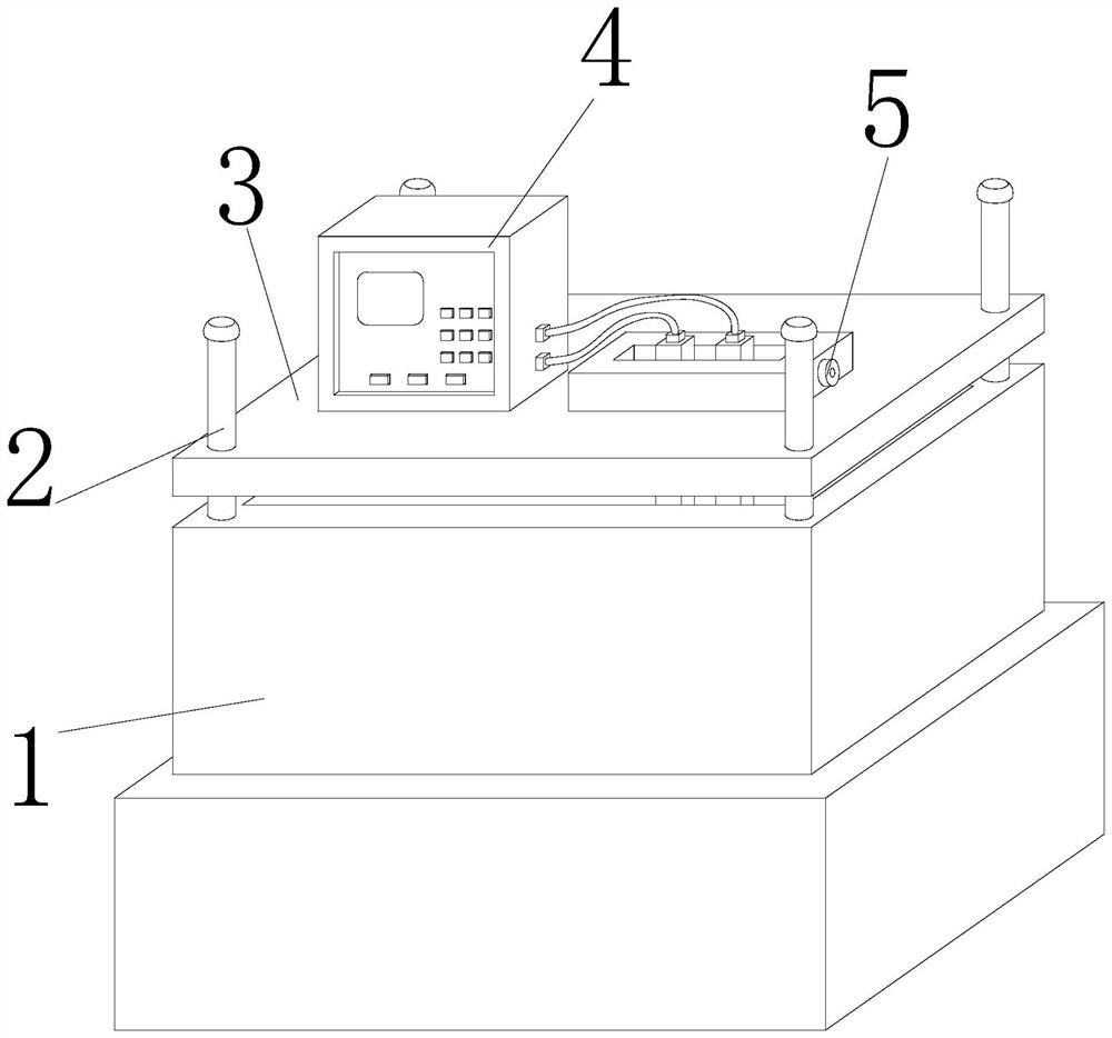
[0028] Such as Figure 1-Figure 5 As shown, the present invention provides a piezoelectric material constant temperature polarization equipment for laboratory use, the structure of which includes a constant temperature chamber 1, a support rod 2, a fixed platform 3, a detector 4, and a polarization device 5, and the bottom end of the support rod 2 is The periphery is embedded in the top four corners of the constant temperature chamber 1, the four corners of the fixed platform 3 are engaged with the periphery of the support rod 2, the lower end of the detector 4 is bolted to the left middle of the upper surface of the fixed platform 3, and the upper part of the polarization device 5 The periphery is embedded and connected to the inner center on the right side of the fixed platform 3 , and the detector 4 is electrically connected to the polarization device 5 .
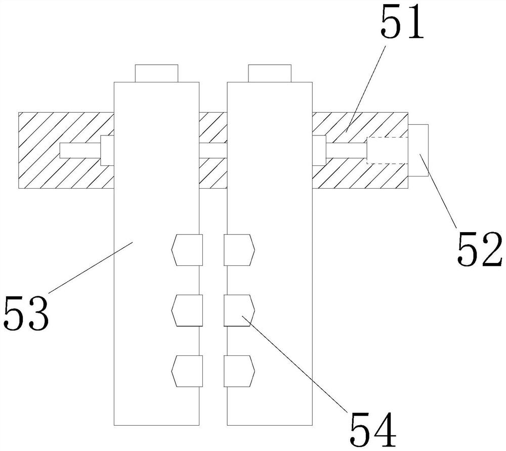
[0029] The polarization device 5 includes an engaging plate 51, an adjusting rod 52, a polarizing plate 53, and a pola...
Embodiment 2
[0036] Such as Figure 6-Figure 8 Shown:
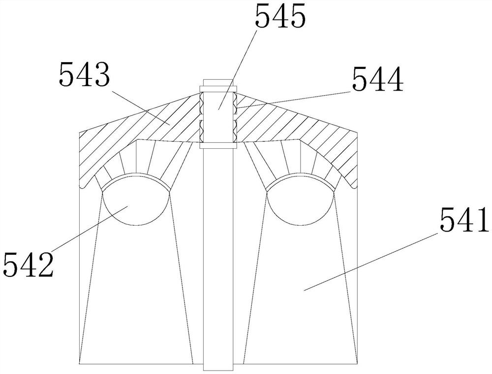
[0037] Wherein, the buffer mechanism 542 includes an upper top block b1, a buffer ball b2, a connecting mechanism b3, a connecting rod b4, and a bottom block b5. The upper end of the buffer ball b2 is fitted inside the center of the lower end of the upper top block b1. The upper end of b3 is embedded and connected to the lower end edge of the upper top block b1, the upper end of the connecting rod b4 is welded to the periphery of the lower end of the connecting mechanism b3, the upper edge of the bottom block b5 is hinged to the end position of the connecting rod b4, and the buffer ball b2 is Soft semi-elliptical spherical structure, which can reduce the impact caused by the impact force when the lower end is quickly approaching, and avoid component damage caused by too fast snapping.
[0038] Wherein, the connection mechanism b3 includes a connection shaft b31, a snap ring b32, a rebound mechanism b33, and a limit case b34. The snap...
PUM
 Abstract
Description
Claims
Application Information
 - R&D
- Intellectual Property
- Life Sciences
- Materials
- Tech Scout
- Unparalleled Data Quality
- Higher Quality Content
- 60% Fewer Hallucinations
Browse by: Latest US Patents, China's latest patents, Technical Efficacy Thesaurus, Application Domain, Technology Topic, Popular Technical Reports.
© 2025 PatSnap. All rights reserved.Legal|Privacy policy|Modern Slavery Act Transparency Statement|Sitemap|About US| Contact US: help@patsnap.com