Automatic assembling equipment for electric connector production and processing

An automatic assembly, electrical connector technology, applied in the assembly/disassembly of contacts, etc., can solve the problems of difficult pin clamping and fixing, lack of production and assembly equipment efficiency and stable production quality, and insulators that cannot be quickly assembled. The effect of less dependence on experience and high degree of automation

Inactive Publication Date: 2021-06-11
江苏富浩电子科技有限公司
View PDF1 Cites 1 Cited by
  • Summary
  • Abstract
  • Description
  • Claims
  • Application Information

AI Technical Summary

Problems solved by technology

[0003] The problem to be solved by the present invention is to provide an automatic assembly equipment for the production and processing of electrical connectors in view of the above-mentioned deficiencies in the prior art, which solves the problem that there is no professional production assembly equipment in the prior art to improve efficiency and stabilize production quality. Problems, especially the problem that the pins are difficult to clamp and fix well when they are inserted through the insulator, and they cannot be quickly assembled with the insulator

Method used


Image

  • Automatic assembling equipment for electric connector production and processing
  • Automatic assembling equipment for electric connector production and processing
  • Automatic assembling equipment for electric connector production and processing

Examples


Embodiment Construction

[0024] In order to make the technical means, creative features, goals and functions achieved by the present invention clearer and easier to understand, the technical solution of the present invention will be described in detail below. Those skilled in the art should know that what are described in the following embodiments are only some specific implementation structures or modes of the present invention, rather than all embodiments, and therefore, the protection scope of the present invention is not limited thereto.

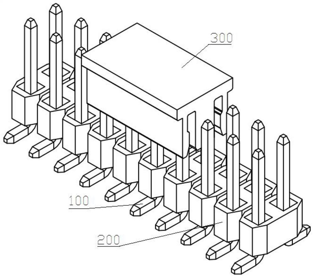
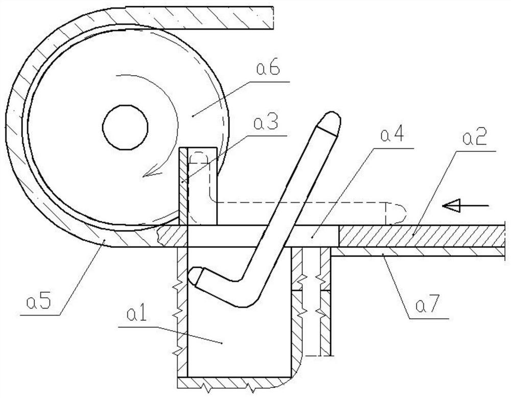
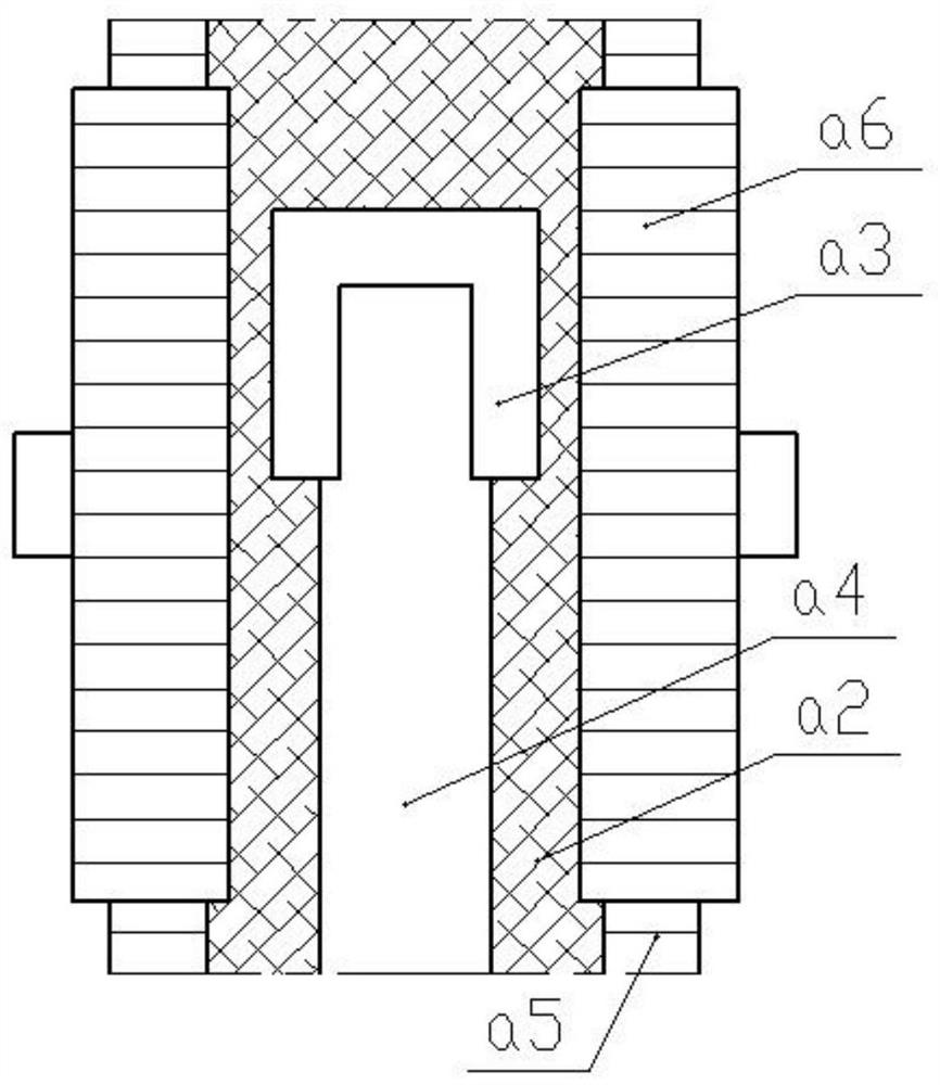
[0025] This embodiment discloses an automatic assembly equipment for the production and processing of electrical connectors. Firstly, it includes an automatic conveying part for conveying the pin 100 into the placement groove a1, see Figure 2-Figure 4 As shown, the structure includes a placement groove a1 for pre-setting the L-shaped pin 100, the placement groove a1 is a flat rectangular parallelepiped structure with an open top. Above the notch of the placemen...


PUM


Abstract

The invention discloses automatic assembling equipment for electric connector production and processing, and the equipment comprises a base with one side provided with an rightward-turned-L-shaped step, a flat rectangular cavity is formed in the vertical side wall of the step in a sunken mode, the height direction of the flat rectangular cavity is the vertical direction, the flat rectangular cavity upwards penetrates through the top face of the base in the height direction, and a second spring plays a role in supporting a movable frame; a blind cavity is formed in the movable frame, the top end of the blind cavity is open, a U-shaped notch is formed in the side wall, facing the outer check block, of the blind cavity, a third spring is vertically installed in the blind cavity, an extrusion rod is further vertically fixed to the side, facing the outer check block, of the movable frame, and a roller is installed at the bottom end of the extrusion rod; a stamping block is installed at the bottom end of the vertical section of the stamping rod and comprises a main block and a sub-block, and the main block and the sub-block are elastically and telescopically connected in the horizontal direction and are located on the same horizontal line all the time. The equipment is simple and practical in structure, and production and assembly of the electric connector can be rapidly and conveniently achieved.

Description

technical field [0001] The invention relates to the field of manufacturing equipment of electrical connectors, in particular to an automatic assembly equipment for production and processing of electrical connectors. Background technique [0002] Electrical connectors are mainly used for line connection of some electrical components, mainly for circuit conduction and signal transmission. An electrical connector structure actually produced in this field is as follows: figure 1 As shown, it includes an insulating cap 300 at the top, an insulating core made of several insulators 200 fixed in series, and several pins 100 shaped like L-shaped rods. Usually, the pins 100 sample a square steel structure Stamped from conductive material. When the electrical connector is assembled, it is mainly divided into three steps: first, the L-shaped pin 100 needs to be transported to the assembly preparation position with the insulator; then, the pin 100 is inserted into the insulator 200 in a...

Claims


Application Information

Patent Timeline
Patent Type & Authority Applications(China)
IPC IPC(8): H01R43/20
CPCH01R43/20
Inventor 许春锋王晓东
Owner 江苏富浩电子科技有限公司
Why Eureka
Try Eureka