
Biradial combined type magnetic pole permanent magnet driving motor

A technology of permanent magnet drive and motor drive, which is applied in the direction of motors, magnetic circuit rotating parts, electric vehicles, etc. It can solve the problems of weak magnetic field strength on both sides of the magnetic pole, high magnetic field strength at the center of the magnetic pole, and weak reliability, and achieve magnetic concentration Significant effect, high power density, and the effect of preventing demagnetization of permanent magnet steel

Inactive Publication Date: 2021-06-11
SHANDONG UNIV OF TECH
View PDF6 Cites 0 Cited by
  • Summary
  • Abstract
  • Description
  • Claims
  • Application Information

AI Technical Summary

Problems solved by technology

[0002] In the current surface-mounted permanent magnet drive motors used in electric vehicles, the surface of the permanent magnet steel is attached to the outer circle of the rotor core. The permanent magnet steel of this structure directly faces the main air gap, which reduces magnetic flux leakage and requires less permanent magnet steel. The structural reliability is weak, and the permanent magnetic field is mainly concentrated in the center of the magnetic pole. The magnetic field strength in the center of the magnetic pole is large, and the magnetic field strength on both sides of the magnetic pole is weak, so that a large static magnetic force is generated in the center of the magnetic pole, resulting in serious pulsation of the drive motor.

Method used


Image

  • Biradial combined type magnetic pole permanent magnet driving motor
  • Biradial combined type magnetic pole permanent magnet driving motor

Examples


Embodiment Construction

[0011] The present invention will be further described below in conjunction with accompanying drawing:

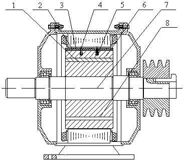
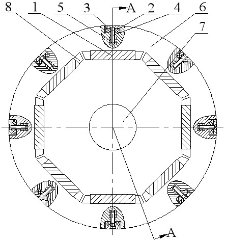
[0012] The double radial combined magnetic pole permanent magnet drive motor is composed of a rotor, a stator, an end cover, and a rotating shaft 7, and is characterized in that: the drive motor rotor is a double radial combined magnetic pole permanent magnet rotor;

[0013] The double radial combined magnetic pole permanent magnet rotor consists of the first rectangular permanent magnet steel 1, the rotor core 6, the pole shoe 3, the second rectangular permanent magnet steel 2, the screw 4, the square iron rivet 5, and the right-angle trapezoidal magnetic isolation air gap 8 , rotating shaft 7, the rotor punch is evenly distributed with a plurality of rectangular slots that are close to the outer circle of the rotor punch and run through the thickness of the rotor punch. The outer side is not connected to the outer circle of the rotor punching sheet. The left end of the re...


PUM


Abstract

The invention provides a biradial combined type magnetic pole permanent magnet driving motor, which belongs to the technical field of electric automobile motor electric appliances. The biradial combined type magnetic pole permanent magnet driving motor consists of a rotor, a stator, an end cover and a rotating shaft, wherein first rectangular permanent magnet steel is radially arranged on the outer side of a rotor core, second rectangular permanent magnet steel fixed by a pole shoe, a screw and a square iron rivet is arranged in the middle of the outer end of the first rectangular permanent magnet steel and divides a magnetic circuit of the first rectangular permanent magnet steel into a left circuit and a right circuit, so that the problem that the magnetic field of the first rectangular permanent magnet steel is concentrated at the magnetic pole center and the magnetic pole center generates large static magnetic force to cause pulsation of a driving motor is avoided, and the pole shoe is additionally arranged at the outer end of the second rectangular permanent magnet steel, thereby ensuring that the second rectangular permanent magnet steel is not demagnetized.

Description

technical field [0001] The invention provides a dual-radial combined magnetic pole permanent magnet drive motor, which belongs to the technical field of electric vehicle motors and appliances. Background technique [0002] In the current surface-mounted permanent magnet drive motors used in electric vehicles, the surface of the permanent magnet steel is attached to the outer circle of the rotor core. The permanent magnet steel of this structure directly faces the main air gap, which reduces magnetic flux leakage and requires less permanent magnet steel. The structural reliability is weak, and the permanent magnetic field is mainly concentrated in the center of the magnetic pole. The magnetic field strength in the center of the magnetic pole is large, and the magnetic field strength on both sides of the magnetic pole is weak, so that a large static magnetic force is generated in the center of the magnetic pole, resulting in serious pulsation of the drive motor. Therefore, mor...

Claims


Application Information

Patent Timeline
IPC IPC(8): H02K1/27H02K1/28
CPCH02K1/27H02K1/28H02K2213/03Y02T10/64
Inventor 耿慧慧张学义胡文静史立伟刘从臻杜钦君王爱传
Owner SHANDONG UNIV OF TECH
Learn More