Flattened ultrasonic motor

An ultrasonic motor, flattening technology, applied in the directions of generators/motors, electrical components, piezoelectric effect/electrostrictive or magnetostrictive motors, etc. To achieve flat structure and other issues, to achieve the effect of broadening the performance adjustment range, small size, and wide adjustment range

Active Publication Date: 2021-06-11
CHONGQING UNIV OF EDUCATION
View PDF13 Cites 1 Cited by
  • Summary
  • Abstract
  • Description
  • Claims
  • Application Information

AI Technical Summary

Problems solved by technology

However, there are often various restrictive factors in the actual processing process. For example, for piezoelectric ceramics, the performance is better and easy to process when the aspect ratio is close to or even exceeds 4. This characteristic makes even in-plane vibration The aspect ratio of the ultrasonic motor still needs to meet certain conditions, and the flat structure cannot be further realized, which limits the further miniaturization of the in-plane vibration ultrasonic motor.

Method used


Image

  • Flattened ultrasonic motor
  • Flattened ultrasonic motor
  • Flattened ultrasonic motor

Examples


Embodiment 2

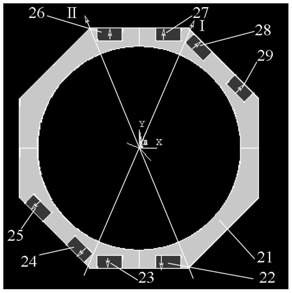
[0034] There is no groove on the stator metal base 21 in Embodiment 1. At this time, the piezoelectric ceramic sheets 22 to 29 are pasted on the outer surface of the stator base 21 by epoxy resin glue, and the piezoelectric ceramics pasted by the stator 12 The positions of the sheets 26 and 27 (22 and 23; 24 and 25; 28 and 29) are close to the two-phase in-plane vibration modes of the stator 12 (such as Figure 4 and Figure 5 shown) in the direction of vibration.

[0035] Similarly, the piezoelectric ceramic sheets 22 to 29 in Embodiment 2 can also be replaced by multilayer stacked piezoelectric ceramics.

[0036] In addition, the embodiment can also figure 2 The position of the piezoelectric ceramic sheets 26 and 27 attached to the stator 12 in the middle is adjusted to be close to the y-axis, and the piezoelectric ceramic sheets 22 and 23 are adjusted successively (close to the y-axis); 24 and 25 (close to the 45° direction); 28 and 29 (close to the 45 ° direction) past...

Embodiment 3

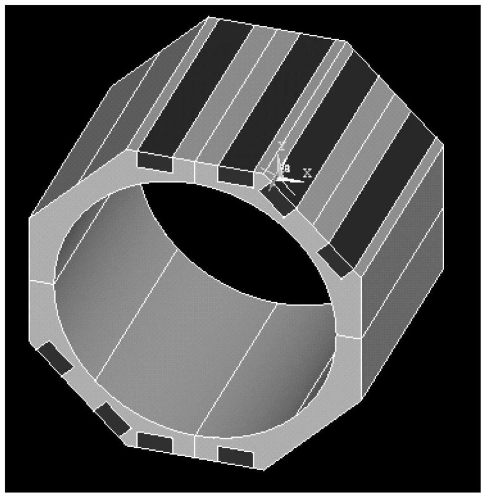
[0038] The number of discrete piezoelectric ceramic sheets is increased on each surface of the stator base 21 in Embodiment 1, thereby further reducing the length of the stator 12 and realizing a flat design of the motor. The number of discrete piezoelectric ceramic sheets on each surface can be between 2 and 5. Usually, the more discrete piezoelectric ceramic pieces on each surface, the smaller the length of the motor, the modal excitation mode of the motor increases exponentially, and the output performance and performance adjustment range of the motor also increase exponentially. The number of piezoelectric ceramic sheets required is also more.

[0039] For the convenience of description, the present invention uses figure 2 The illustrated stator base is taken as an example for illustration, but the flattened design proposed by the present invention is also applicable to in-plane vibration ultrasonic motors working in other in-plane vibration modes.


PUM


Abstract

The invention discloses a flattened ultrasonic motor, which relates to the field of ultrasonic motors and is characterized by comprising a shaft, a stator, a rotor, a disc spring and a nut, wherein the stator is of a hollow structure, the stator comprises a stator metal matrix and a plurality of discrete piezoelectric ceramics, and the piezoelectric ceramics are symmetrically arranged on the stator metal matrix; the rotor is of a conical structure and is arranged on the upper end face of the stator; the nut is connected with the rotor through the disc spring; and the shaft penetrates through the stator. According to the flattened ultrasonic motor, an original single piezoelectric ceramic piece is replaced by a plurality of discrete piezoelectric ceramic pieces, so that the in-plane vibration type ultrasonic motor achieves flat design, and the improved ultrasonic motor is easy to achieve and convenient to operate; and the ultrasonic motor is further miniaturized, the output displacement of the motor is improved, the excitation mode of the motor is increased, the performance adjusting range of the motor is widened, and a driving control circuit of the motor is simplified.

Description

technical field [0001] The invention relates to the field of ultrasonic motors, in particular to a flattened ultrasonic motor. Background technique [0002] Due to the characteristics of compact structure, easy processing, low cost, simple modal excitation, easy miniaturization and high energy density, ultrasonic motors have been widely used in precision drives and semiconductor industries. Ultrasonic motors based on in-plane vibration have received extensive attention due to their strong driving capabilities. In-plane vibration-type ultrasonic motors use the in-plane vibration of the stator body. Therefore, theoretically, the stator of this type of ultrasonic motor can be designed as a thin sheet. However, there are often various restrictive factors in the actual processing process. For example, for piezoelectric ceramics, the performance is better and easy to process when the aspect ratio is close to or even exceeds 4. This characteristic makes even in-plane vibration The...

Claims


Application Information

Patent Timeline
Patent Type & Authority Applications(China)
IPC IPC(8): H02N2/12H02N2/14
CPCH02N2/12H02N2/14
Inventor 裴军芳李志佘远俊张霖
Owner CHONGQING UNIV OF EDUCATION
Why Eureka
Try Eureka