
Strip slitting device and strip slitting method

A die-cutting and cutting technology, used in work accessories, manufacturing tools, stone processing tools, etc., can solve the problems of reduced production capacity, scattered processes, waste of manpower and material resources, etc.

Active Publication Date: 2021-06-15
LANS INTELLIGENT ROBOT CHANGSHA CO LTD
View PDF13 Cites 0 Cited by
  • Summary
  • Abstract
  • Description
  • Claims
  • Application Information

AI Technical Summary

Problems solved by technology

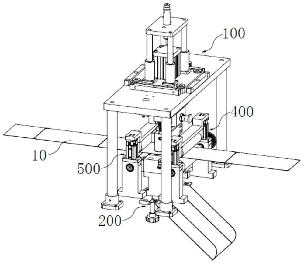
[0005] The object of the present invention is to provide a strip material cutting device and a strip material cutting method, so as to alleviate the slicing process of the slicing process for processing the back cover panel in the prior art, which wastes a lot of manpower and material resources, resulting in a high production capacity. Reduced technical issues

Method used


Image

  • Strip slitting device and strip slitting method
  • Strip slitting device and strip slitting method
  • Strip slitting device and strip slitting method

Examples


Embodiment Construction

[0056] In order to make the purpose, technical solutions and advantages of the embodiments of the present invention clearer, the technical solutions in the embodiments of the present invention will be clearly and completely described below in conjunction with the drawings in the embodiments of the present invention. Obviously, the described embodiments It is a part of embodiments of the present invention, but not all embodiments. The components of the embodiments of the invention generally described and illustrated in the figures herein may be arranged and designed in a variety of different configurations.

[0057] Accordingly, the following detailed description of the embodiments of the invention provided in the accompanying drawings is not intended to limit the scope of the claimed invention, but merely represents selected embodiments of the invention. Based on the embodiments of the present invention, all other embodiments obtained by persons of ordinary skill in the art wi...


PUM


Abstract

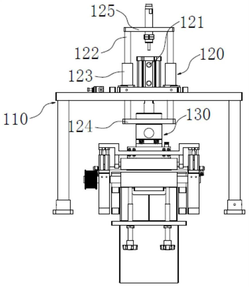
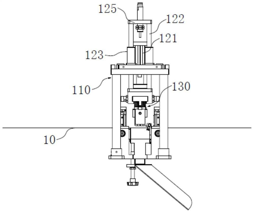
The invention provides a strip slitting device and a strip slitting method, and relates to the technical field of strip machining equipment. The strip slitting device comprises an upper die assembly and a lower die assembly. The upper die assembly comprises a support, a driving assembly and a die cutting assembly, and the driving assembly is in transmission connection with the die cutting assembly. The die cutting assembly comprises a first floating pressing block, a second floating pressing block and a fillet slitting waste kicking die. The lower die assembly comprises a lower die base, a fixed lower die and a floating lower die. A concave cavity for enabling the fillet die cutting part to perform die cutting on a fillet material of the strip is formed between the fixed lower die and the floating lower die. A rear cover panel is formed by slitting by the strip slitting device. An electronic product comprises a back cover panel. According to the strip slitting method, the strip slitting device is used for slitting. By means of the strip slitting device, the technical problems that in the prior art, procedures of a slicing process for machining the rear cover panel are scattered, a large amount of manpower and material resources are wasted, and the productivity is reduced are solved.

Description

technical field [0001] The invention relates to the technical field of strip material processing equipment, in particular to a strip material cutting device and a strip material cutting method. Background technique [0002] With the increasing requirements of electronic products for signal transmission, ceramic materials have gradually become a An important choice for the differentiation of electronic products. [0003] At present, some electronic products mostly use ceramic materials as the back cover panel. In the process of ceramic material processing, the ceramic material needs to be melt-blown into a soft strip, and then cut into the shape of the mobile phone back cover, and then hardened. The shape of the ceramic slice is finished. During this process, it is necessary to carry out continuous and precise cutting of the ceramic strip, so that the remaining semi-finished waste in the subsequent hardening and finishing process is the least, which not only saves processin...

Claims


Application Information

Patent Timeline
IPC IPC(8): B28D1/22B28D7/00B28D7/04
CPCB28D1/22B28D7/00B28D7/04Y02P70/10
Inventor 冯金果
Owner LANS INTELLIGENT ROBOT CHANGSHA CO LTD
Learn More