Combined leakage stoppage method for local leakage in foundation pit

A plugging method and technology for foundation pits, which are applied in excavation, infrastructure engineering, construction, etc., can solve problems such as soil flow damage, safety impact of foundation pits, and inability to perform normal construction, achieve rapid precipitation, and ensure construction progress and safety. , The purposeful effect of the water cutoff range

Inactive Publication Date: 2021-06-15
CCCC SHANGHAI THIRD HARBOR SCI RES INST CO LTD +1
View PDF3 Cites 1 Cited by
  • Summary
  • Abstract
  • Description
  • Claims
  • Application Information

AI Technical Summary

Problems solved by technology

The rainwater pump house that passes through the tunnel is a typical pit-in-pit. There is a deep pit at the bottom of the foundation pit, and the geological soil layer where the retaining piles are not successfully overlapped is mainly silt and sand. Partial seepage in the pit-in-pit Leakage is large, resulting in flow soil damage, unable to carry out normal construction
At this time, the water level of the foundation pit cannot be lowered to the bottom of the pit, so it is difficult to continue excavation. Long-term leakage will affect the safety of the foundation pit, and the existing plugging technology is difficult to achieve rapid plugging for normal construction operations.

Method used


Image

  • Combined leakage stoppage method for local leakage in foundation pit
  • Combined leakage stoppage method for local leakage in foundation pit
  • Combined leakage stoppage method for local leakage in foundation pit

Examples


Embodiment Construction

[0029] The following will clearly and completely describe the technical solutions in the embodiments of the application with reference to the drawings in the embodiments of the application. Apparently, the described embodiments are only some of the embodiments of the application, not all of them. Based on the embodiments in this application, all other embodiments obtained by persons of ordinary skill in the art without making creative efforts belong to the scope of protection of this application.

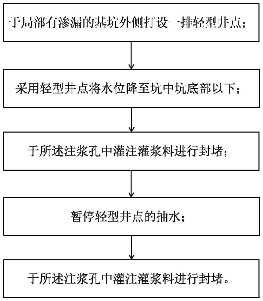
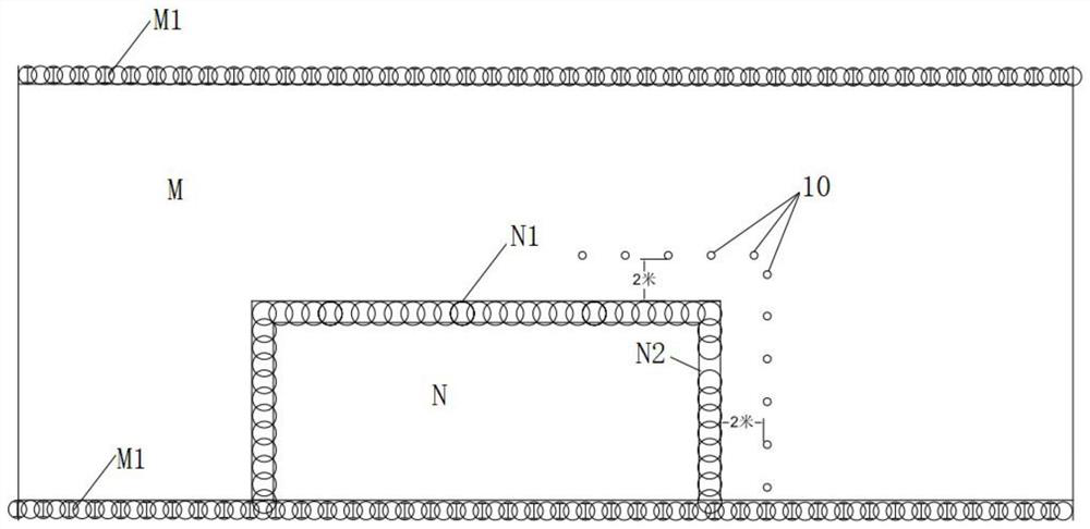
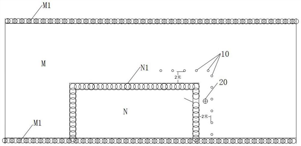
[0030] Such as Figure 1 to Figure 3 As shown, in one of the embodiments of the present application, a joint leakage plugging method for local leakage in foundation pits, including:

[0031] Set up a row of light well points 10 outside the foundation pit M with local leakage;

[0032] Use the light well point 10 to lower the water level below the bottom of the pit-in-pit N;

[0033] Drill the grouting hole 20;

[0034] Suspension of pumping at light well point 10;

[0035] The g...


PUM


Abstract

The invention discloses a combined leakage stoppage method for local leakage in a foundation pit. The combined leakage stoppage method comprises the steps that a row of light well points are arranged on the outer side of the foundation pit with local leakage; the water level is lowered below the bottom of a pit-in-pit by adopting the light well points; a grouting hole is formed; water pumping of the light well points is suspended; and grouting materials are poured into the grouting hole for blocking. According to the combined leakage stoppage method, the method for locally forming a water reduction curtain at the light well points is adopted, and a water interception curtain is rapidly formed, so that the water level is rapidly and locally lowered to the bottom end of the pit; then a grouting material grouting method is used for rapidly blocking the leakage point, and therefore, the purpose of leakage stoppage is achieved; and the light well points and the double-liquid grouting material are used for grouting and leakage stoppage, and more pertinence on the conditions that the pit-in-pit exists at the bottom of the foundation pit, and a geological soil layer where fender posts are not successfully overlapped is mainly silty soil and silty sand is achieved.

Description

technical field [0001] The application belongs to the technical field of leakage plugging in foundation pits, and in particular relates to a joint plugging method for local leakage in foundation pits. Background technique [0002] With the continuous development of traffic construction, more and more underpass tunnels are being built in cities. The rainwater pump house passing through the tunnel is a typical pit-in-pit. There is a deep pit at the bottom of the foundation pit, and the geological soil layer where the retaining piles are not successfully overlapped is mainly silt and sand. Partial seepage in the pit-in-pit Leakage is large, resulting in flow soil damage, unable to normal construction. At this time, the water level of the foundation pit cannot be lowered to the bottom of the pit, so it is difficult to continue excavation. Long-term leakage will affect the safety of the foundation pit, and the existing plugging technology is difficult to achieve fast plugging fo...

Claims


Application Information

Patent Timeline
Patent Type & Authority Applications(China)
IPC IPC(8): E02D19/10E02D19/18E02D17/02
CPCE02D19/10E02D19/18E02D17/02
Inventor 林文朱寅杨建明徐铁铮龚济平王雷胡小波贾涛
Owner CCCC SHANGHAI THIRD HARBOR SCI RES INST CO LTD
Why Eureka
Try Eureka