Power Design Method for Injection Molded Parts and Its Heating Tube

An injection mold and heating tube technology, applied in the field of molds, can solve the problems of uneven heating of molding materials and difficulty in setting heating tube components.

Active Publication Date: 2022-02-01
GREE ELECTRIC APPLIANCES INC
View PDF8 Cites 0 Cited by
  • Summary
  • Abstract
  • Description
  • Claims
  • Application Information

AI Technical Summary

Problems solved by technology

[0003] However, when the mold body has multiple cavities, improper power setting of the heating pipe assembly will easily lead to uneven heating of the molding materials in each cavity. In practice, in order to make the molding materials in each cavity evenly heated, it is often necessary The layout position and power of the heating tubes were corrected many times, which made it difficult to set up the heating tube components

Method used


Image

  • Power Design Method for Injection Molded Parts and Its Heating Tube
  • Power Design Method for Injection Molded Parts and Its Heating Tube
  • Power Design Method for Injection Molded Parts and Its Heating Tube

Examples


Embodiment Construction

[0024] Embodiment of the Power Design Method of Injection Mold Parts and Its Heating Tubes:

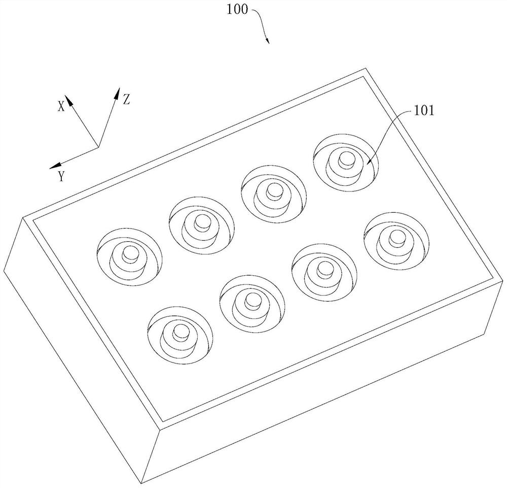
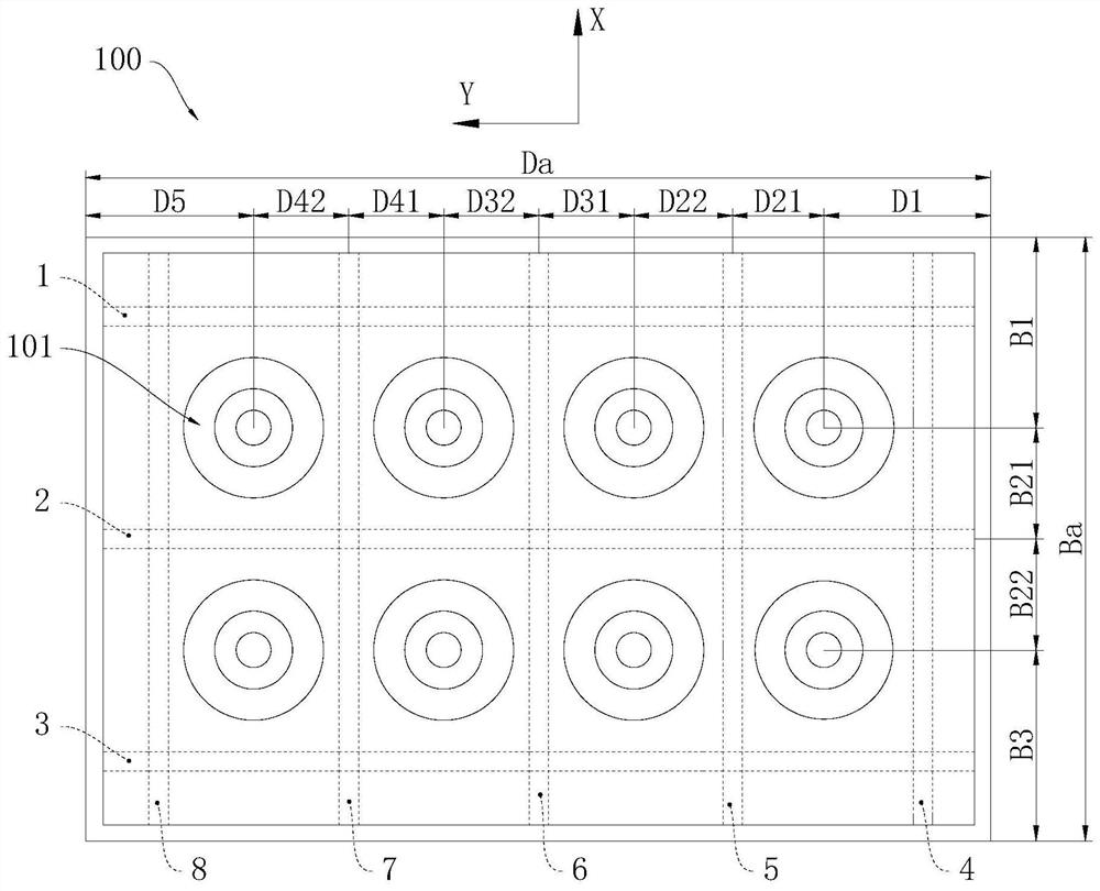
[0025] In this example figure 1 and figure 2 Using a unified space right-angle coordinate system (right hand strainer) to indicate the relative position relationship between components, where the X-axis direction is the first direction, the Y-axis direction is the second direction, the Z-axis direction is a third direction.

[0026] The injection molding member of the present embodiment is the first half die 100, and the first half die 100 is used to form an injection mold with the second semi-mold, and the first half die 100 and the second semi-mold are distributed in the Z-axis direction, the first half mode. The 100 molding cavity is surrounded between the second half, and the eight molding cavities are divided into two rows distributed in the X-axis direction, each of which has four in the Y-axis direction.

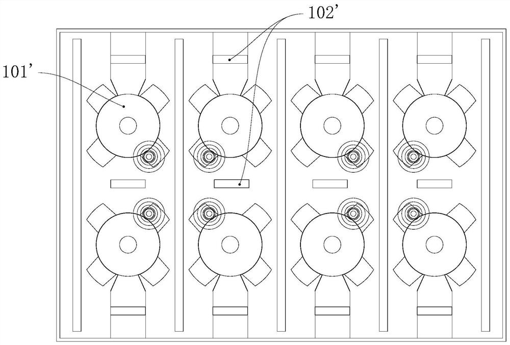
[0027] The first half die 100 is provided with eight heating tubes on the se...


PUM


Abstract

The invention relates to the field of moulds, and provides a power design method for injection mold parts and heating pipes thereof. The injection mold part provided by the present invention includes a mold body and a plurality of heating pipes. The mold body has a plurality of first mold cavities distributed in m rows and n columns. The first mold cavities in each row are distributed along the first direction, and the first mold cavities in each row are first The mold cavity is distributed along the second direction, at least m+1 of the multiple heating tubes are distributed into m+1 rows along the first direction, and at least n+1 of the multiple heating tubes are distributed into n+1 along the second direction The plurality of heating tubes encloses m×n spaces, and each first cavity corresponds to each space one by one. The present invention designs the power relationship of each heating tube according to the dimensional parameters among the first cavity, the end face and the heating tube, which not only helps to make each first cavity receive uniform heating, but also helps to improve the molding quality, and also helps to reduce heating The number of design experiments of the tubes is beneficial to quickly determine the power of each heating tube.

Description

Technical field [0001] The present invention relates to the field of molds, and in particular to a power design method of injection molding components and its heating tubes. Background technique [0002] The mold mainly includes a mold and a heating tube assembly, a mold having a cavity, a heating tube assembly generating heat to heat the molding material in the mold cavity. [0003] However, in the case where the mold has a plurality of cavities, the power setting of the heating tube assembly can easily lead to uneven heat in each molding material, in order to make the molded material in each of the mold cavities are uniform, often need Multiple experimental corrections in the arrangement position and power of the heating tube, resulting in a large set of difficulty in the heating tube assembly. Inventive content [0004] One of the objects of the present invention is to provide an injection molding member that is simple and facilitating uniform thermally heat in the first mold...

Claims


Application Information

Patent Timeline
Patent Type & Authority Patents(China)
IPC IPC(8): B29C45/73B29C45/26
CPCB29C45/7331B29C45/2602B29C2045/2651
Inventor 于博骆玉叶张健
Owner GREE ELECTRIC APPLIANCES INC
Why Eureka
Try Eureka