
Control system and control method

A control system and control unit technology, applied in lighting circuits, signal devices, etc., can solve the problems of low robustness of the ambient light control system, poor heat dissipation of RGB-LED lamp beads, etc., and achieve low cost and simple circuit design cost. Low, robustness-enhancing effect

Pending Publication Date: 2021-06-18
CHANGZHOU XINGYU AUTOMOTIVE LIGHTING SYST CO LTD
View PDF0 Cites 0 Cited by
  • Summary
  • Abstract
  • Description
  • Claims
  • Application Information

AI Technical Summary

Problems solved by technology

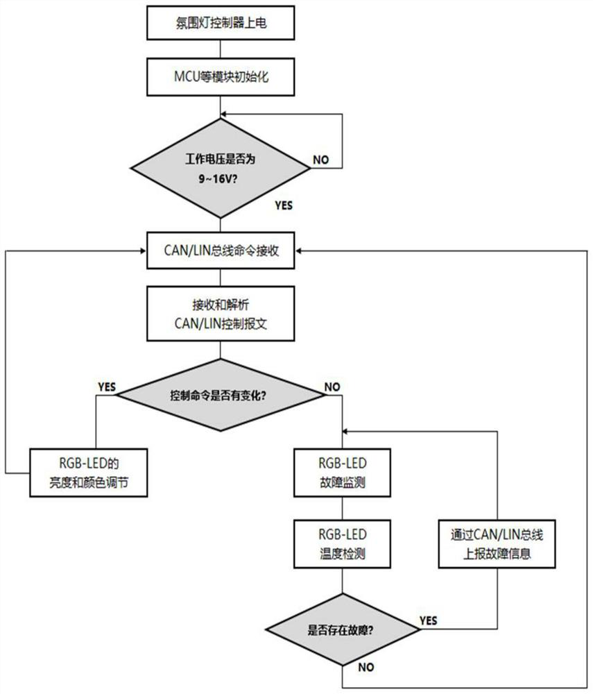
[0003] The invention discloses a control system. The control system is applied to the control of ambient light, which solves the limitation of the number of RGB-LED lamp beads in the existing ambient light control system and provides a dynamic ambient light control system. The whole system theoretically supports Up to 4096 RGB-LED lamp beads, and then through the control of the different colors and brightness of each RGB-LED lamp bead, the dynamic atmosphere lighting effect is realized; the control system is applied to the over-temperature protection of the atmosphere lamp, which solves the problem of large number of The RGB-LED lamp bead has poor heat dissipation in a small space, which can easily lead to the problem of overheating, which can protect the dynamic atmosphere lamp from overheating and effectively reduce the failure of the dynamic atmosphere lamp due to excessive temperature; the control The system is applied to dynamic ambient light fault detection, which solves the problem of weak robustness of the existing ambient light control system, provides a dynamic ambient light fault detection system, realizes effective fault management of dynamic ambient light, and enhances dynamic atmosphere Robustness of the lamp system

Method used


Image

  • Control system and control method
  • Control system and control method
  • Control system and control method

Examples


Embodiment Construction

[0029] Embodiments of the present invention are described in detail below, examples of which are shown in the drawings, wherein the same or similar reference numerals designate the same or similar elements or elements having the same or similar functions throughout. The embodiments described below by referring to the figures are exemplary only for explaining the present invention and should not be construed as limiting the present invention.

[0030] Embodiments of the present invention will be described in detail below in conjunction with the accompanying drawings.

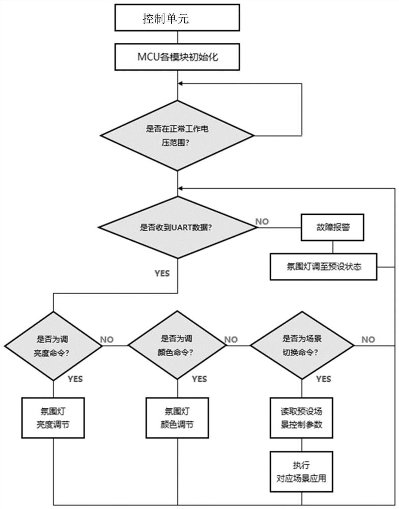
[0031] Apply the control system of the present invention to dynamic ambient light control, see figure 1 , including the control unit and RGB-LED lamp beads.

[0032] control unit

[0033] The control unit includes an MCU chip, at least one control mode of the ambient light is preset in the MCU chip, and the control mode is selected according to an actual command. Preferably, the MCU chip is S32K144-64PIN, and ...


PUM


Abstract

The invention discloses a control system and a control method. The control system comprises an upper computer, a control unit and an execution unit. The upper computer is used for sending a control command and receiving state information from the execution unit; the control unit receives a control command of the upper computer and is used for controlling the execution unit; the execution unit is used for executing the control command of the control unit; the control unit comprises a CAN transceiver and an MCU chip, and the CAN transceiver is used for receiving a control command from the upper computer in real time and sending state information of the execution unit to the upper computer; the MCU chip reads the state information of the execution unit through a signal line and feeds back the state information of the execution unit to the CAN transceiver. The control system can be applied to dynamic atmosphere lamp control, dynamic atmosphere lamp over-temperature protection and dynamic atmosphere lamp fault monitoring, and belongs to the field of intelligent control of automobile electronic lighting systems.

Description

technical field [0001] The invention relates to the field of intelligent control of automotive electronic lighting systems, in particular to a control system and a control method. Background technique [0002] With the rapid development of automotive electronics technology, more and more attention has been paid to the technology of automotive interior lighting. Automotive ambient light is an automotive interior lighting system that creates and decorates various interior lighting scenes. As a new type of interior decoration light, the ambient light can not only adjust the light color and light intensity of the interior decoration lights in real time, but also meet the dynamic lighting in the car under different conditions. Nowadays, LIN communication is mostly used to control the ambient light. In LIN communication, each controller can only connect 16 nodes, and the number of LED lamp beads connected to each node is usually less than 12. Therefore, the traditional ambient lig...

Claims


Application Information

Patent Timeline
Patent Type & Authority Applications(China)
IPC IPC(8): B60Q3/80B60Q11/00
CPCB60Q11/005B60Q3/80
Inventor 徐健
Owner CHANGZHOU XINGYU AUTOMOTIVE LIGHTING SYST CO LTD
Learn More