Aircraft part assembly closed angle region riveting inclined riveting card design method

An aircraft component and design method technology, applied in the field of aircraft component assembly tool design, can solve problems such as fatigue fracture of oblique rivets, and achieve the effects of obvious service life, broad application and promotion prospects, and reduced assembly costs.

Active Publication Date: 2021-06-18
CHENGDU AIRCRAFT INDUSTRY GROUP
View PDF19 Cites 0 Cited by
  • Summary
  • Abstract
  • Description
  • Claims
  • Application Information

AI Technical Summary

Problems solved by technology

[0005] The purpose of the present invention is to provide a design method for riveting oblique riveting clips in closed angle areas of aircraft parts assembly, which can effectively solve the problem of potential fatigue fractures caused by insufficient design of oblique riveting clips, ensure assembly quality, improve assembly efficiency, and reduce assembly costs

Method used


Image

  • Aircraft part assembly closed angle region riveting inclined riveting card design method
  • Aircraft part assembly closed angle region riveting inclined riveting card design method
  • Aircraft part assembly closed angle region riveting inclined riveting card design method

Examples


Embodiment 1

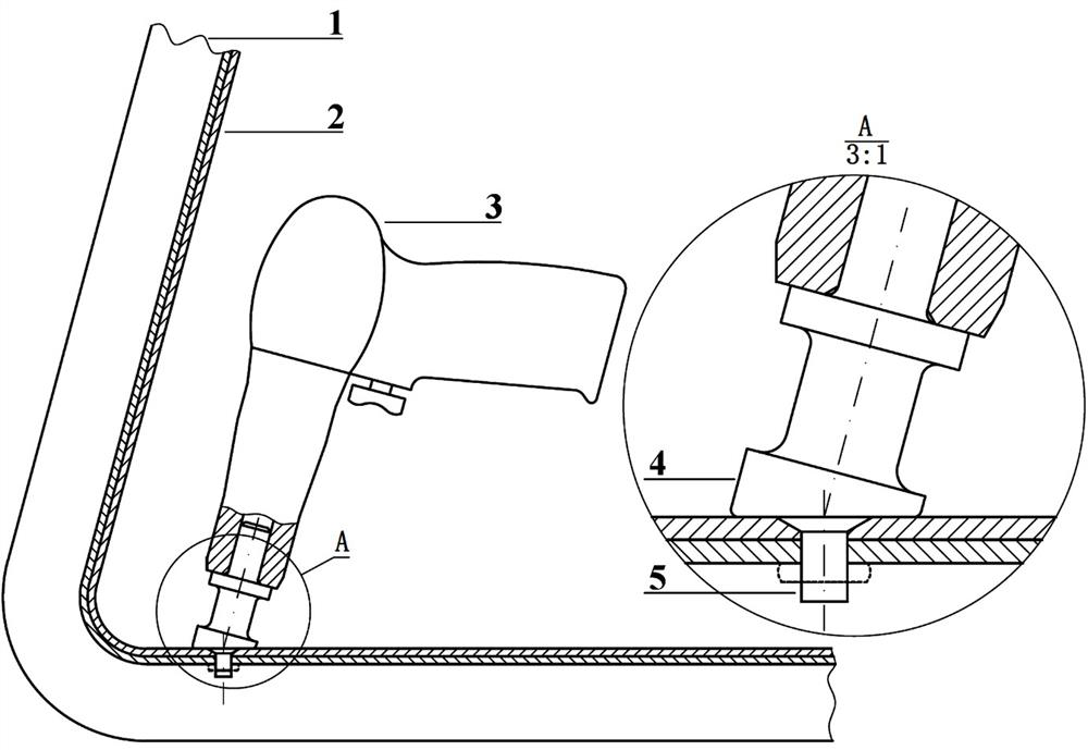
[0037] This embodiment takes the aircraft of a certain model in our company as the research object, and now it is necessary to close the closed angle area (generally, the angle between two adjacent sides on the structure is less than 90°) in the aircraft structure. The area is called the closed angle area) for riveting operation, it is necessary to design the oblique riveting card that conforms to the riveting environment.

[0038] This embodiment proposes a design method for riveting oblique riveting in the closed angle area of ​​aircraft component assembly, which belongs to the technical field of aircraft component assembly tool design, and specifically includes the following steps:

[0039] A. Construct a geometric model according to the structural characteristics of the aircraft's closed corner area. The geometric primitives in the geometric model include bulkheads, skins, rivets, oblique rivets, and rivet guns. Refer to figure 1 , and select the relevant physical feature...

Embodiment 2

[0054] On the basis of Example 1, this embodiment further studies the oblique riveting card, details the design process of this technical solution, provides a basis for the design and manufacturing size of the oblique riveting card, and provides certainty for further research on this technology. It also provides a new design scheme for reference for the manufacture of such tools.

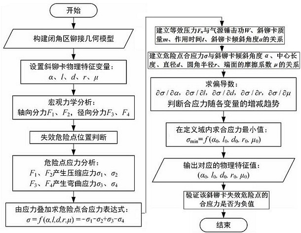
[0055] A method for designing oblique riveting clips for riveting in closed angle areas of aircraft component assembly, belonging to the technical field of aircraft component assembly tool design, referring to image 3 , including the following steps:

[0056] (1) Construct a geometric model according to the structural characteristics of the closed angle area of ​​the aircraft. The geometric primitives in the geometric model include bulkheads, skins, rivets, oblique rivets and rivet guns, and select the relevant geometric primitives Physical characteristics as independent variables, the independent...


PUM


Abstract

The invention discloses a design method for riveting an inclined riveting clamp in an aircraft part assembly closed angle region, and belongs to the technical field of aircraft part assembly tool design. A geometric model of the aircraft closed angle region is constructed, macroscopic mechanical analysis is conducted on the inclined riveting clamp, and the inclined angle alpha, the center length l and the diameter d of the inclined riveting clamp are selected; the method comprises the following steps: taking the root fillet radius r of the inclined riveting clamp and the friction coefficient mu of the end face of the riveting clamp as independent variables, researching the relationship between the air source hammering work W, the riveting clamp mass m and the action time t and the independent variables, and finally determining the value of the independent variables in the definition domain range of the independent variables as the reference size of the design of the inclined riveting clamp. The problem of fatigue fracture hidden danger caused by insufficient design of the inclined riveting clamp is effectively solved, the assembly quality is guaranteed, the assembly efficiency is improved, and the assembly cost is reduced.

Description

technical field [0001] The invention relates to the technical field of aircraft component assembly tool design, in particular to a design method for riveting oblique riveting clips in closed angle areas of aircraft component assembly. Background technique [0002] The aircraft component assembly takes the airframe structure as the research object, and connects the skeleton parts and the outer cladding parts into segments with the aerodynamic shape of the aircraft. In aircraft assembly mechanical connection technology, riveting is widely used for its simple operation, reliable connection, convenient inspection, easy troubleshooting, and ability to adapt to relatively complex and not open space structures. The typical area with poor spatial openness in the aircraft structure is the closed angle area of ​​the structure (specifically refers to the area where the angle between two adjacent sides of the structure is less than 90°). Limited by the interference of the space structu...

Claims


Application Information

Patent Timeline
Patent Type & Authority Applications(China)
IPC IPC(8): B64F5/00B64F5/10
CPCB64F5/00B64F5/10
Inventor 龙安林卢大伟陈昶杨博
Owner CHENGDU AIRCRAFT INDUSTRY GROUP
Why Eureka
Try Eureka