Well cementation sliding sleeve with pressure compensation structure

A pressure compensation, sliding sleeve technology, applied in wellbore/well components, wellbore/well valve devices, sealing/packing, etc., can solve the problems of sticking, high cost, uncontrollable delay time, etc. On-time controllable effects

Active Publication Date: 2021-06-18
PETROCHINA CO LTD
View PDF5 Cites 0 Cited by
  • Summary
  • Abstract
  • Description
  • Claims
  • Application Information

AI Technical Summary

Problems solved by technology

[0003] There are several problems in the coiled tubing transmission perforation method in the first section: 1. The operation time is long, and the first section of perforation will take more than a few days. Low efficiency; 2. A lot of equipment needs to be mobilized, such as cranes, pump trucks, etc., which are expensive and prone to risks such as pipe sticking, self-locking, and falling objects; 3. Coiled tubing operations such as deep wells, ultra-long horizontal wells, and upturned wells The tool is difficult to go down to the bottom of the well, and the effective horizontal section length cannot be guaranteed
[0004]Currently, the domestic cementing sliding sleeve technology has problems such as inaccurate cracking pressure control, uncontrollable delay time, low cracking success rate, etc., especially in shale gas wells In the deep layers of unconventional oil and gas wells, the cementing sleeve is often unable to open due to high pressure.

Method used


Image

  • Well cementation sliding sleeve with pressure compensation structure
  • Well cementation sliding sleeve with pressure compensation structure
  • Well cementation sliding sleeve with pressure compensation structure

Examples


Embodiment 1

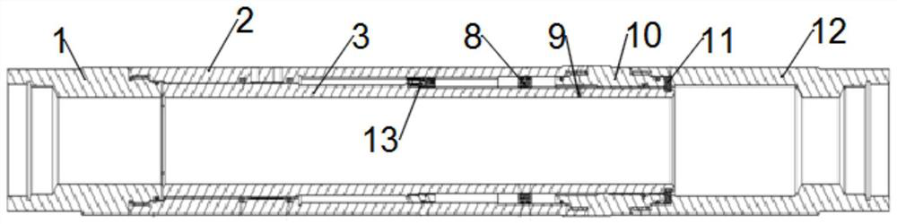
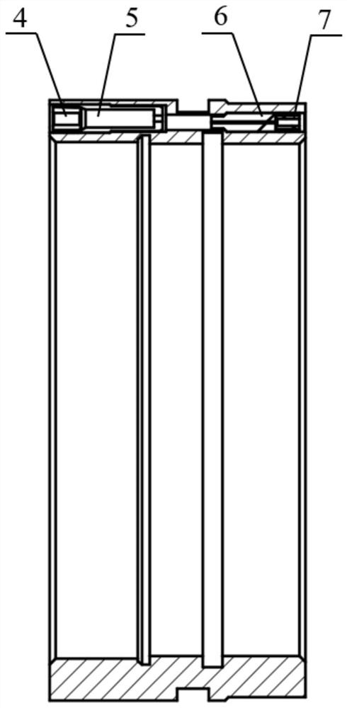
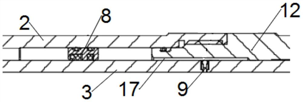
[0038] Such as Figure 1 ~ 5 As shown, the present invention has a solid well slip cover with a pressure compensation structure. The working principle of the solid ceiling sleeve of the pressure compensation mechanism is that the blasting valve 9 opens when the hydraulic pressure in the wellbore rises to the blasting valve 9 burst. The high-pressure liquid enters the slit 17 between the birds 13 and the inner slide 3 by the blasting valve 9, so that the inner skirt 3 has a pressure balance, avoiding the deep pressure of the oil and gas well, causing the slide jaw, can't start The piston set 8 separates the high pressure liquid to the original liquid in the liquid cavity, and balances the pressure of the two, and the pressure of the wellbore continues to increase in the wellbore to the high pressure liquid cavity, and after the shear ring 11 is predetermined, shear The ring 11 is cut, and then activated by a single flow valve stabilizer 4, a single flow valve 5, a current limiting v...


PUM


Abstract

The invention discloses a well cementation sliding sleeve with a pressure compensation structure. The well cementation sliding sleeve comprises a well cementation sliding sleeve body composed of an upper connector, an outer sliding sleeve, an inner sliding sleeve, a lower connector and a double-male short section, and further comprises a throttling system, a piston sleeve, an explosion valve and a shearing ring; and the throttling system and the piston sleeve are both arranged in a cavity, the explosion valve can communicate with a shaft space and a cavity space, and the shearing ring is arranged at the bottom end of the inner sliding sleeve. According to the well cementation sliding sleeve, the pressure of the inner surface and the outer surface of the inner sliding sleeve reaches the pressure balance state through the explosion valve, and the problem that the sliding sleeve is stuck and cannot be opened due to the fact that the pressure of a deep layer section of an oil and gas well is too high can be effectively prevented; the pressure of the sliding sleeve during opening can be accurately controlled by adjusting the pre-cut-off value of the shearing ring; and the throttling system composed of a check valve, a flow limiting valve and the like can control the opening time by controlling the flowing speed of liquid in a precursor, and thus the purpose that the opening time is controllable is achieved.

Description

Technical field [0001] The present invention is designed to have an oil and gas well-operated work tool, which specifically relates to a solid skit thereof with a pressure compensation structure. Background technique [0002] At present, the first segment hole is usually used in front of the first layer of fracturing passage before the fracturing construction is carried out. After the first layer fracturing channel is established, the bridge is pumped to the sleeve in the sleeve. Carry out the next paragraph fracturing trial. [0003] There are several aspects of the first segment of the continuous tubing in the first paragraph: 1. Long work hours, the first shooting hole will take a few days, the operation is low; 2. Multi-equipment, cranes, pump trucks need to be mobilized Waiting, cost, easy to have a risk of card diamond, self-locking, and falling or other; 3, deep well, ultra-long horizontal sector, superior horizontal segment, superiors, etc., etc. The first fracturing cons...

Claims


Application Information

Patent Timeline
Patent Type & Authority Applications(China)
IPC IPC(8): E21B34/14E21B34/08E21B33/13
CPCE21B34/14E21B34/08E21B33/13
Inventor 李明范宇张华礼尹强谢南星喻成刚付玉坤帅春岗易德正喻冰
Owner PETROCHINA CO LTD
Why Eureka
Try Eureka