Optical element contour detection method and device based on fringe tracking and storage medium

A technology for optical components and contour detection, applied in neural learning methods, using optical devices, measuring devices, etc., can solve problems such as insufficient precision, detection range that cannot reach a large range, and insufficient dynamic range.

Active Publication Date: 2021-06-18
CHANGCHUN INST OF OPTICS FINE MECHANICS & PHYSICS CHINESE ACAD OF SCI
View PDF9 Cites 1 Cited by
  • Summary
  • Abstract
  • Description
  • Claims
  • Application Information

AI Technical Summary

Problems solved by technology

These methods have their own shortcomings, such as insufficient precision, the detecti

Method used


Image

  • Optical element contour detection method and device based on fringe tracking and storage medium
  • Optical element contour detection method and device based on fringe tracking and storage medium
  • Optical element contour detection method and device based on fringe tracking and storage medium

Examples


Embodiment Construction

[0038] The following will clearly and completely describe the technical solutions in the embodiments of the present invention with reference to the accompanying drawings in the embodiments of the present invention. Obviously, the described embodiments are only some, not all, embodiments of the present invention. Based on the embodiments of the present invention, all other embodiments obtained by persons of ordinary skill in the art without making creative efforts belong to the protection scope of the present invention.

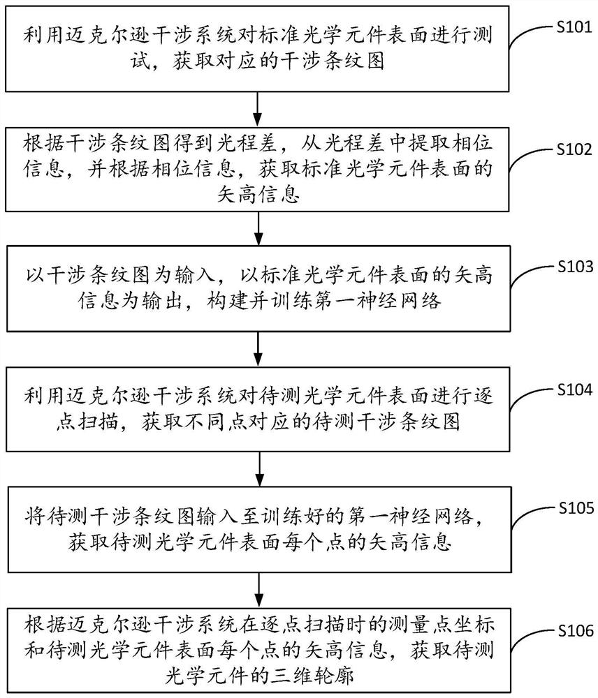
[0039] The invention provides a method for detecting the contour of an optical element based on fringe tracking, such as figure 1 shown, including the following steps:

[0040] S101. Using a Michelson interference system to test the surface of a standard optical element to obtain a corresponding interference fringe pattern.

[0041] It should be noted that the standard optical element can be a standard plane mirror with a better surface shape, so as to obtain...


PUM


Abstract

The invention discloses an optical element contour detection method and device based on fringe tracking and a storage medium, and the method comprises the steps: testing the surface of a standard optical element through a Michelson interference system, and obtaining an interference fringe pattern; obtaining an optical path difference according to the interference fringe pattern, extracting phase information from the optical path difference, and obtaining vector height information of the surface of the standard optical element according to the phase information; constructing and training a first neural network by taking the interference fringe pattern as input and taking vector height information of the surface of the standard optical element as output; similarly, performing point-by-point scanning on the surface of the to-be-measured optical element to obtain a to-be-measured interference fringe pattern; inputting the to-be-measured interference fringe pattern into a first neural network, and obtaining vector height information of each point on the surface of the to-be-measured optical element; and obtaining the three-dimensional contour of the to-be-measured optical element according to the measurement point coordinates of the Michelson interference system during point-by-point scanning and the vector height information of each point on the surface of the to-be-measured optical element. The detection method is wide in detection range and high in measurement precision.

Description

technical field [0001] The invention relates to the field of surface shape detection, in particular to a fringe tracking-based optical element profile detection method, device and storage medium. Background technique [0002] For the measurement of the free-form surface shape of the high-precision, large-scale optical elements in the synthetic aperture telescope, its accuracy is probably below 1 micron and above 50 nanometers. However, on the meter-scale scale, there is still no good method for detecting such changes at the micron level with sub-micron level accuracy. [0003] In the prior art, surface measurement mainly aimed at free-form surfaces is generally performed using computer-generated holograms (Computer-Generated Holograms, CGH), swing-arm profilers, laser trackers, or sub-aperture splicing methods. These methods have their own shortcomings, such as insufficient precision, the detection range cannot reach a large range, and the dynamic range is not enough when m...

Claims


Application Information

Patent Timeline
IPC IPC(8): G01B11/24G06N3/04G06N3/08
CPCG01B11/2441G06N3/04G06N3/08
Inventor 安其昌刘欣悦李洪文王越
Owner CHANGCHUN INST OF OPTICS FINE MECHANICS & PHYSICS CHINESE ACAD OF SCI
Why Eureka
Try Eureka