
Patsnap Eureka
For R&D, Patsnap Eureka makes reading and utilizing patents & technical documents easy.
Patsnap Eureka AIR
Designed for self-driven R&D workflows. Generate viable solutions, solve complex R&D challenges, empower your innovation with AI.

Patsnap Eureka Materials
Designed for material experts only. Revolutionize your material R&D, from search, analyze, to developing new materials.

TechResearch
Generate reliable direction feasibility study reports for your R&D in just a few steps.

TechSeek
Discover and master advanced knowledge NOW. Basics, ideas, possibilities, all at once.

TechMind
As an expert in R&D Theories, TechMind can generates customized viable solutions instantly.

TechRisk
Analyze your overall solution with one click, know your potential R&D risks in advance.

TechMonitor
Get weekly tech updates, stay abreast of the latest tech innovations and key insights.
Optical sensing system and optical navigation system
a technology of optical sensing and optical navigation, applied in image enhancement, instruments, image data processing, etc., can solve the problems of time-consuming and expensive methods, and the need for objects, and achieve the effect of reducing time and cos
- Summary
- Abstract
- Description
- Claims
- Application Information
AI Technical Summary
Benefits of technology
Problems solved by technology
Method used
Image

Examples
Embodiment Construction
[0016]Several embodiments are provided in following descriptions to explain the concept of the present invention. Each component in following descriptions can be implemented by hardware (e.g. a device or a circuit) or hardware with software (e.g. a program installed to a processor). Besides, the method in following descriptions can be executed by programs stored in a non-transitory computer readable recording medium such as a hard disk, an optical disc or a memory. Besides, the term “first”, “second”, “third” in following descriptions are only for the purpose of distinguishing different one elements, and do not mean the sequence of the elements. For example, a first device and a second device only mean these devices can have the same structure but are different devices.
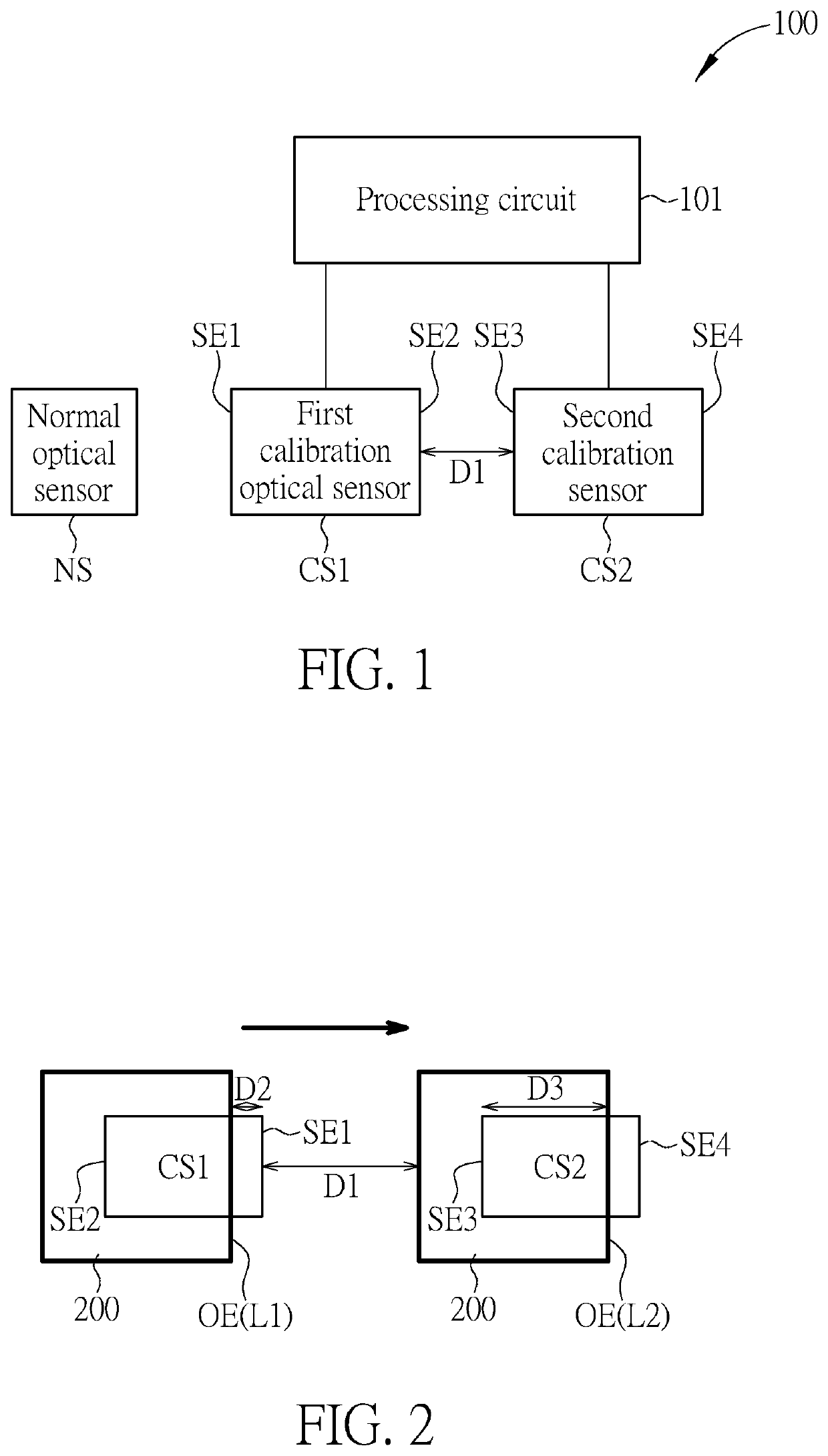
[0017]FIG. 1 is a block diagram illustrating an optical sensing system according to one embodiment of the present invention. As illustrated in FIG. 1, the optical sensing system 100 comprises a processing circuit 101 ...
PUM
 Abstract
Description
Claims
Application Information
 - R&D Engineer
- R&D Manager
- IP Professional
- Industry Leading Data Capabilities
- Powerful AI technology
- Patent DNA Extraction
Browse by: Latest US Patents, China's latest patents, Technical Efficacy Thesaurus, Application Domain, Technology Topic, Popular Technical Reports.
© 2024 PatSnap. All rights reserved.Legal|Privacy policy|Modern Slavery Act Transparency Statement|Sitemap|About US| Contact US: help@patsnap.com