Method for manufacturing optical lens with frosted interface

a manufacturing method and optical lens technology, applied in the direction of instruments, soldering apparatus,auxillary welding devices, etc., can solve the problems of affecting the clarity of imaging, affecting the accuracy of optical lenses, and affecting the quality of optical lenses, so as to improve clarity and imaging quality, avoid margin tolerance, and reduce the interference of stray light

Inactive Publication Date: 2018-09-13
GENIE PRECISION MACHINING
View PDF0 Cites 1 Cited by
  • Summary
  • Abstract
  • Description
  • Claims
  • Application Information

AI Technical Summary

Benefits of technology

[0010]The advantage of the present invention is utilizing the laser to laser-mark the interior of the optical lens. Then the frosted interface is formed on the marginal light trace inside the optical lens. The frosted interface may reduce light penetrating into the optically effective portion from the outer portion. The frosted interface may reduce the interference of stray light from the outer portion, hence enhancing clarity and imaging quality.
[0011]Particularly, before aligning the marginal light trace between the optically effective portion and the outer portion of the optical lens to the laser instrument, the method comprises providing a positioning structure around the optical lens. The positioning structure comprises multiple connecting blocks and at least one positioning member. The multiple connecting blocks are mounted on an outer surface of the optical lens, and the at least one positioning member connects to sides of the multiple connecting blocks that are distal from the optical lens. The advantage of the present invention is utilizing the positioning structure around the optical lens to help regulate the alignment of the optical lens and the laser instrument.
[0012]More particularly, after forming the frosted interface on the marginal light trace by the laser beam induced from the laser instrument, the

Problems solved by technology

The stray light can interfere with a light directly emitted into the optically effective portion 102 and affect the clarity of imaging.
Furthermore, the stray light may also i

Method used


Image

  • Method for manufacturing optical lens with frosted interface
  • Method for manufacturing optical lens with frosted interface
  • Method for manufacturing optical lens with frosted interface

Examples


first embodiment

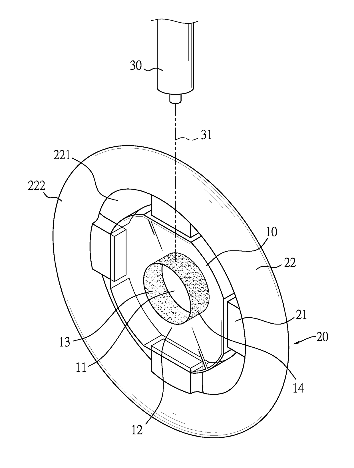
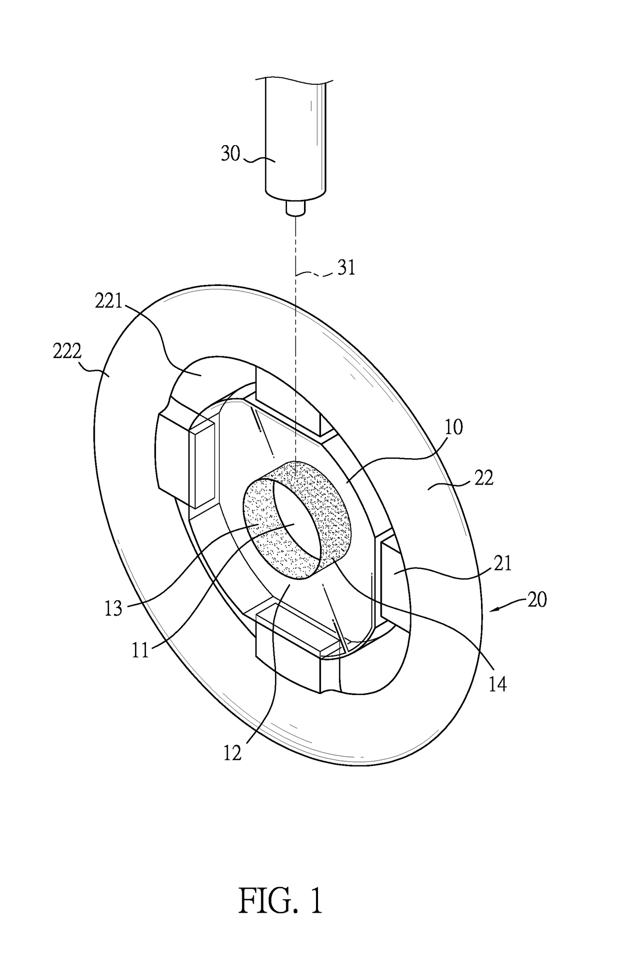
[0024]With reference to FIGS. 1 and 2, the present invention provides a positioning structure 20 around an optical lens 10. The optical lens 10 comprises an optically effective portion 11 and an outer portion 12. The positioning structure 20 comprises four connecting blocks 21 and a positioning member 22. The four connecting blocks 21 are mounted on an outer surface of the outer portion 12 at spaced intervals. The positioning member 22 connects to the four connecting blocks 21 at sides of the connecting blocks that are distal from the outer portion 12 of the optical lens 10. The optical lens 10, the four connecting blocks 21, and the positioning member 22 are integrated. The positioning member 22 is a ring. The positioning member 22 comprises an inner edge 221 and an outer edge 222. The inner edge 221 connects to the four connecting blocks 21 at the sides of the four connecting blocks that are distal from the outer portion 12 of the optical lens 10.

[0025]After the above the optical ...

second embodiment

[0027]With reference to FIG. 4, the present invention provides a positioning structure 20A around an optical lens 10. The optical lens 10 comprises an optically effective portion 11 and an outer portion 12. The positioning structure 20A comprises four connecting blocks 21A and four positioning members 22A. The four connecting blocks 21A are mounted on the outer surface of the outer portion 12 at spaced intervals. The four positioning members 22A each respectively connect to the four connecting blocks 21A at the sides of the four connecting blocks 21A that are distal from the outer portion 12 of the optical lens 10. The positioning members 22A are balls. The optical lens 10, the four connecting blocks 21 A, and the four positioning members 22 A are integrated.

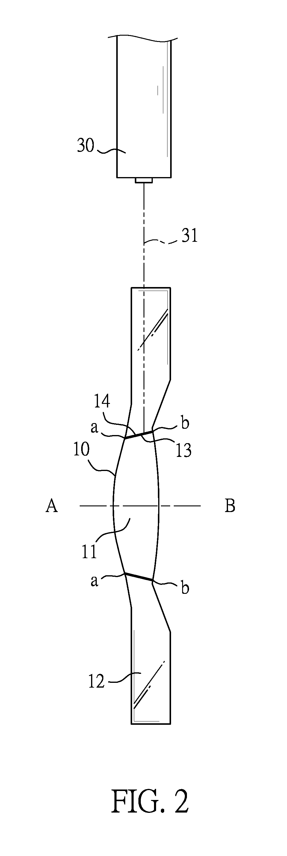
[0028]After the above the optical lens 10 and the positioning structure 20A are fixed, a marginal light trace 13 between the optically effective portion 11 and the outer portion 12 of the optical lens 10 are aligned to a laser i...


PUM


Abstract

Provided is a method for manufacturing an optical lens with a frosted interface. The frosted interface is formed by laser marking between an optically effective portion and an outer portion on the optical lens. The frosted interface may resist a stray light emitted from the outer portion. This prevents the stray light from penetrating into the optically effective portion and affecting the imaging. Furthermore, also provided is a positioning structure around the optical lens. The positioning structure can help to align the optical lens and a laser instrument. Then the frosted interface can be manufactured between the optically effective portion and the outer portion accurately by the above positioning structure. The frosted interface within the optical lens enhances the imaging quality.

Description

BACKGROUND OF THE INVENTION1. Field of the Invention[0001]The present invention relates to a method for manufacturing an optical lens, and more particularly to a method for manufacturing an optical lens with a frosted interface.2. Description of the Related Art[0002]With reference to FIG. 5, a conventional camera lens 90 comprises multiple optical lenses 100. Each of the optical lenses 100 comprises an optical axis 101, an optically effective portion 102, and an outer portion 103. The optical axis 101 is on the center of the optical lenses 100. The optically effective portion 102 is used for imaging. The outer portion 103 is formed around an outer surface of the optically effective portion 102 and is used for stacking with neighboring optical lenses 100 and fixing the optical lenses 100 on a frame 91. A marginal light trace 104 is formed between the optically effective portion 102 and the outer portion 103. The marginal light trace 104 is a connecting line between a marginal optical...

Claims


Application Information

Patent Timeline
IPC IPC(8): G02B5/02B23K26/00B23K26/53B23K37/04
CPCG02B5/0268G02B5/021G02B5/0236B23K2103/54B23K26/53B23K26/0006B23K37/0426B23K26/0057G02B5/0231
Inventor CHANG, YU SHENG
Owner GENIE PRECISION MACHINING
Why Eureka
Try Eureka