
Electric meter with real-time monitoring function

A technology of real-time monitoring and ammeters, applied in the direction of measuring electrical variables, closed-circuit television systems, measuring time integration, etc., can solve the problems of lack of relevant circuit knowledge and difficult statistics of stolen power, and achieve the effect of strong concealment

Inactive Publication Date: 2021-06-18
侯晓珠
View PDF0 Cites 0 Cited by
  • Summary
  • Abstract
  • Description
  • Claims
  • Application Information

AI Technical Summary

Problems solved by technology

[0003] Traditional electric meters are installed directly in the electric meter box, which is very vulnerable to electricity stealing operations by criminals. Electricity stealing refers to the illegal use of electric energy for the purpose of not paying or paying less electricity bills. The behavior of stealing electricity, the existing means of stealing electricity is mainly to open or destroy the meter box by modifying the wiring of the meter or the internal circuit structure, directly connecting the power supply from other meters or reducing the meter’s measurement of the amount of electricity used, so as to achieve the purpose of paying less electricity bills Small amounts of electricity theft are often difficult to find through statistical big data. After users discover it, there is little direct evidence to identify the suspect due to lack of relevant circuit knowledge, and it is difficult to count the stolen electricity.

Method used

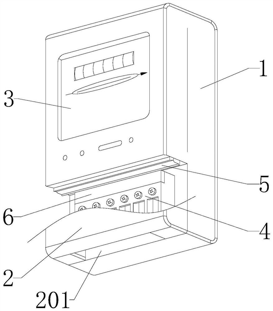
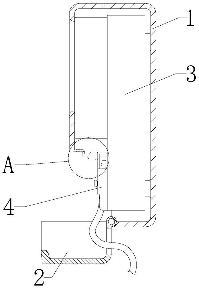
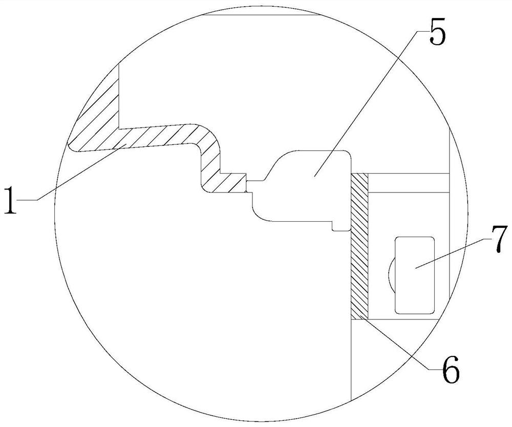

Image

  • Electric meter with real-time monitoring function
  • Electric meter with real-time monitoring function
  • Electric meter with real-time monitoring function

Examples


Embodiment Construction

[0024] The following will clearly and completely describe the technical solutions in the embodiments of the present invention with reference to the accompanying drawings in the embodiments of the present invention. Obviously, the described embodiments are only some, not all, embodiments of the present invention. Based on the embodiments of the present invention, all other embodiments obtained by persons of ordinary skill in the art without making creative efforts belong to the protection scope of the present invention.

[0025] Unless otherwise defined, the technical terms or scientific terms used in the present disclosure shall have the usual meanings understood by those skilled in the art to which the present disclosure belongs. The words "comprising" or "comprising" and similar words used in the present disclosure mean that the elements or things appearing before the word include the elements or things listed after the word and their equivalents, without excluding other elem...


PUM


Abstract

The invention provides an electric meter with a real-time monitoring function, which comprises a shell, wherein a dust cover which can be turned over to be opened is hinged to the bottom of the shell, a wire passing groove for wire passing is formed in the lower end of the dust cover, an electric meter main body is fixed in the shell, a wiring end is arranged at the lower end of the electric meter main body, a camera shooting unit facing the front face of the electric meter is embedded in the top of the wiring end, a shielding plate is arranged on the front side of the camera shooting unit to shield the camera shooting unit, and an illuminating lamp is fixed to the position, which is obliquely in front of the camera shooting unit, of the shell structure. According to the invention, a magnet and a magnetic attraction switch are arranged in the dust cover and the shell, when an operator opens the dust cover to operate wiring of an electric meter, the magnetic attraction switch loses the effect of the magnet to achieve connection so as to supply power to an LED lamp strip and the camera shooting unit, the LED lamp strip is turned on, the wiring end is illuminated, the wiring operation of the operator is facilitated, the face of the operator is illuminated, the electrified camera shooting unit shoots clear face data of the operator, the electricity stealing person can be distinguished conveniently, and the good development prospect is achieved.

Description

technical field [0001] The invention relates to the field of power supply, in particular to an electric meter with real-time monitoring. Background technique [0002] The electric meter, also known as the electric meter, is one of the basic equipment for smart grid data collection. It undertakes the tasks of raw electric energy data collection, measurement and transmission, and is the basis for information integration, analysis optimization and information presentation. [0003] Traditional electric meters are installed directly in the electric meter box, which is very vulnerable to electricity stealing operations by criminals. Electricity stealing refers to the illegal use of electric energy for the purpose of non-payment or less payment of electricity bills. The behavior of stealing electricity, the existing means of stealing electricity is mainly to open or destroy the meter box by modifying the wiring of the meter or the internal circuit structure, directly connecting th...

Claims


Application Information

Patent Timeline
Patent Type & Authority Applications(China)
IPC IPC(8): G01R11/04H04N7/18
CPCG01R11/04H04N7/18
Inventor 侯晓珠
Owner 侯晓珠
Learn More