
Backlight module and electronic equipment

A technology for backlight modules and astigmatism components, applied in optics, nonlinear optics, instruments, etc., can solve the problems of large shading black border width and low screen ratio, and achieve small shading black border width, high screen ratio, Improve the screen-to-body ratio

Pending Publication Date: 2021-06-18
VIVO MOBILE COMM CO LTD
View PDF13 Cites 1 Cited by
  • Summary
  • Abstract
  • Description
  • Claims
  • Application Information

AI Technical Summary

Problems solved by technology

[0005] The purpose of the embodiment of the present application is to provide a backlight module and electronic equipment, which can solve the problems of the backlight module in the prior art that have a large width of the shading black border and a low screen-to-body ratio

Method used


Image

  • Backlight module and electronic equipment
  • Backlight module and electronic equipment

Examples


Embodiment Construction

[0015] The following will clearly and completely describe the technical solutions in the embodiments of the present application with reference to the drawings in the embodiments of the present application. Obviously, the described embodiments are part of the embodiments of the present application, not all of them. Based on the embodiments in this application, all other embodiments obtained by persons of ordinary skill in the art without creative efforts fall within the protection scope of this application.

[0016] The terms "first", "second" and the like in the specification and claims of the present application are used to distinguish similar objects, and are not used to describe a specific sequence or sequence. It should be understood that the terms so used are interchangeable under appropriate circumstances such that the embodiments of the application can be practiced in sequences other than those illustrated or described herein, and that references to "first," "second," et...


PUM


Abstract

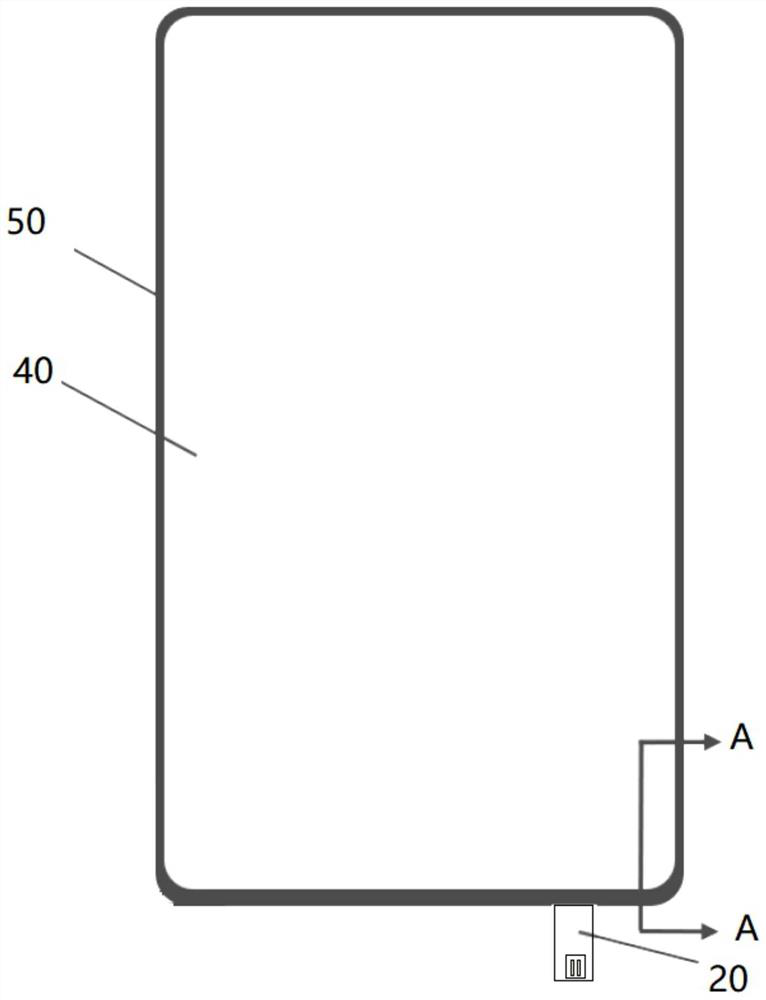
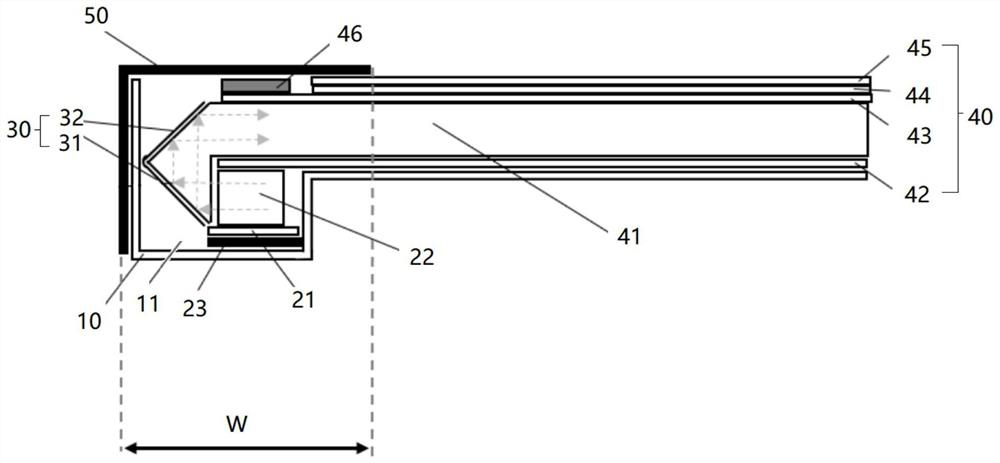
The invention discloses a backlight module and electronic equipment, and belongs to the technical field of electronic equipment. The backlight module comprises an installation frame, a light source, a light guide assembly and a light scattering assembly, the installation frame is provided with an installation groove, the installation groove is located in the light emitting side of the backlight module, the light source is installed in the installation groove, the light guide assembly is at least partially located in the installation groove, and the light guide assembly is used for guiding light emitted by the light source to the light scattering assembly; wherein the light scattering assembly is used for scattering light rays emitted by the light source to a backlight display area. The backlight module has the advantages that the width of the shading black edge of the backlight module is smaller, and the screen-to-body ratio of the display screen is high.

Description

technical field [0001] The application belongs to the technical field of electronic equipment, and in particular relates to a backlight module and electronic equipment. Background technique [0002] With the rapid development of the electronic equipment industry, consumers have higher and higher requirements for the screen ratio of the display screen. Taking mobile phones as an example, the display screens of some mobile phones are liquid crystal displays (Liquid Crystal Display, LCD), and the traditional LCD screens are under great pressure. [0003] In the advanced technology, LCD screens have also introduced various solutions to increase the screen-to-body ratio, such as Chip On Flex (or, Chip On Film, commonly referred to as COF) structure, narrow borders, etc. [0004] However, an important bottleneck in improving the screen-to-body ratio of LCD screens is that the width of the black border in the light-mixing area on the light incident side of the backlight is relativ...

Claims


Application Information

Patent Timeline
IPC IPC(8): G02F1/13357
CPCG02F1/133615
Inventor 王智雄张武峰
Owner VIVO MOBILE COMM CO LTD
Learn More