
A multifunctional experimental instrument for university physics and electromagnetism

An experimental instrument and electromagnetism technology, which is applied in the direction of instruments, supporting machines, machine tables/stands, etc., can solve the problems of electromagnetic experiment instruments, such as complicated size, inconvenient cleaning, and tired teachers, so as to achieve multi-scenario multi-functional use and improve Improve user experience and improve the scope of application

Active Publication Date: 2022-03-04
TONGJI UNIV
View PDF8 Cites 1 Cited by
  • Summary
  • Abstract
  • Description
  • Claims
  • Application Information

AI Technical Summary

Problems solved by technology

[0003] However, the electromagnetic experiment instruments are complicated and vary in size. When teaching the experimental instruments in the laboratory, the experimental teachers mostly hold the experimental instruments with their hands so that the students can see the experimental equipment clearly, or put large experimental instruments on the table to explain , there are certain disadvantages in both cases
In the former method, the teacher is very tired and can’t do other things with one hand occupied; in the latter method, it is difficult to realize multi-angle display of the instrument, it is inconvenient to adjust the angle, and it is easy to fall dust when the oscilloscope is not used, which is not easy to clean

Method used


Image

  • A multifunctional experimental instrument for university physics and electromagnetism
  • A multifunctional experimental instrument for university physics and electromagnetism
  • A multifunctional experimental instrument for university physics and electromagnetism

Examples


Embodiment

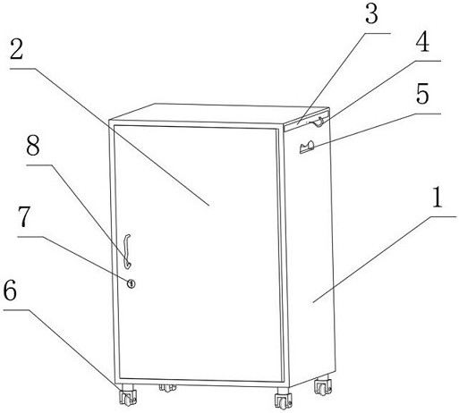
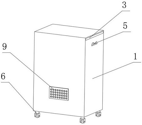
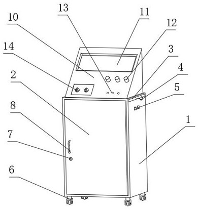
[0023] see Figure 1-Figure 6 , the present invention provides the following technical solutions: in the present embodiment, a kind of university physics and electromagnetics multifunctional experimental instrument comprises cabinet 1 and shell 10, and the inside of cabinet 1 is equipped with the mounting plate 15 that has support column 16, and mounting plate 15 The motor 17 is installed on the bottom surface of the mounting plate 15, and the four corners of the top surface of the mounting plate 15 are equipped with a lifting column 21 with a synchronous plate 26. A spring 27 is installed, which increases the stability of the device and helps the synchronous plate 26 to control the synchronous movement of the lifting column 21. The top surface of the synchronous plate 26 is equipped with a suction cup 25. The suction cup 25 not only plays the role of pre-fixing the shell 10, but also supports it. The role of the shell 10, the top surface of the cabinet 1 is equipped with a du...


PUM


Abstract

The invention belongs to the technical field of experimental instruments, in particular to a multifunctional experimental instrument for university physics and electromagnetism, comprising a cabinet and a casing, a mounting plate is installed inside the cabinet, and a lifting column with a synchronizing plate is installed on the four corners of the top surface of the mounting plate; The bottom surface of the outer casing is provided with a connecting column with a limiting slot, and a clamping assembly is installed between the outer casing and the synchronizing plate; the clamping assembly includes a limit block and a two-way screw, and the two-way screw is pierced with two limiters for fixing the connecting column. Position block; a lifting column with a synchronizing plate and a spring is installed inside the device cabinet. The spring assists the synchronizing plate to adjust the movement direction, which is convenient for the lifting column to adjust the height of the instrument and achieve the best viewing angle; when idle, the lifting column will store the instrument into the cabinet. The oscilloscope can be easily fixed by the clamping components, and the suction cups on the synchronization board play the role of pre-fixation and support buffer, which is convenient for installation and disassembly, improves the applicable scope of the instrument, and realizes the multi-scenario and multi-functional use of the instrument.

Description

technical field [0001] The invention belongs to the technical field of experimental instruments, and in particular relates to a multifunctional experimental instrument for university physics and electromagnetism. Background technique [0002] With the continuous development of natural science, experimental instruments are very important. In electrical professional experiments, oscilloscopes are electromagnetic experiments. Oscilloscopes are electronic measuring instruments with a wide range of uses. It can transform electrical signals invisible to the naked eye. To form a visible image, the oscilloscope uses a narrow electron beam composed of high-speed electrons to hit the screen coated with fluorescent substances to produce tiny light spots. Under the action of the measured signal, the electron beam draws the change curve of the instantaneous value of the measured signal on the screen. [0003] However, the electromagnetic experiment instruments are complicated and vary i...

Claims


Application Information

Patent Timeline
Patent Type & Authority Patents(China)
IPC IPC(8): G09B19/00F16M11/32F16M11/42
CPCG09B19/00F16M11/32F16M11/42
Inventor 赫丽张冶文方恺孙勇李云辉
Owner TONGJI UNIV
Learn More