
Motor stator and motor

A motor and stator technology, applied in the field of motors, can solve the problems of affecting the full rate of the slot, affecting the performance of the motor, increasing the iron loss, etc., to achieve the effect of ensuring the connection stability, ensuring the performance of the motor, and avoiding the increase of the iron loss.

Pending Publication Date: 2021-06-18
SUZHOU AICHI TECH CO LTD
View PDF0 Cites 0 Cited by
  • Summary
  • Abstract
  • Description
  • Claims
  • Application Information

AI Technical Summary

Problems solved by technology

[0004] 1) There is at most one groove for fixing the insulating frame on the end face of the stator core on each toothed unit of the stator core. In order to minimize the loss of magnetic flux, the groove is too small, which may easily cause the insulating frame to fail Fully fixed on the end face of the stator core, it may shake or even fall off due to instability
[0005] 2) When winding on the insulating frame that cannot be sufficiently fixed on the end face of the stator core, the insulating frame is easily deformed and damaged due to the stress of the winding, and the front end of the tooth of the insulating frame is easy to warp, which affects the slot fill rate. affect the performance of the motor
[0006] 3) Grooves are set at positions with high magnetic density such as the teeth, yoke, and tooth roots of the stator core, resulting in increased iron loss, and the higher the magnetic density, the greater the iron loss.
[0007] 4) Setting grooves at positions with high magnetic density such as the teeth, yoke, and tooth roots of the stator core will hinder the flow of magnetic lines of force and affect the performance of the motor

Method used


Image

  • Motor stator and motor
  • Motor stator and motor
  • Motor stator and motor

Examples


Embodiment Construction

[0046] Embodiments of the present invention are described in detail below, and examples of the embodiments are shown in the drawings, wherein the same or similar reference numerals denote the same or similar elements or elements having the same or similar functions throughout. The embodiments described below by referring to the figures are exemplary and are intended to explain the present invention and should not be construed as limiting the present invention.

[0047] In the description of the present invention, it should be noted that the terms "center", "upper", "lower", "left", "right", "vertical", "horizontal", "inner", "outer" etc. The indicated orientation or positional relationship is based on the orientation or positional relationship shown in the drawings, and is only for the convenience of describing the present invention and simplifying the description, rather than indicating or implying that the referred device or element must have a specific orientation, or in a s...


PUM


Abstract

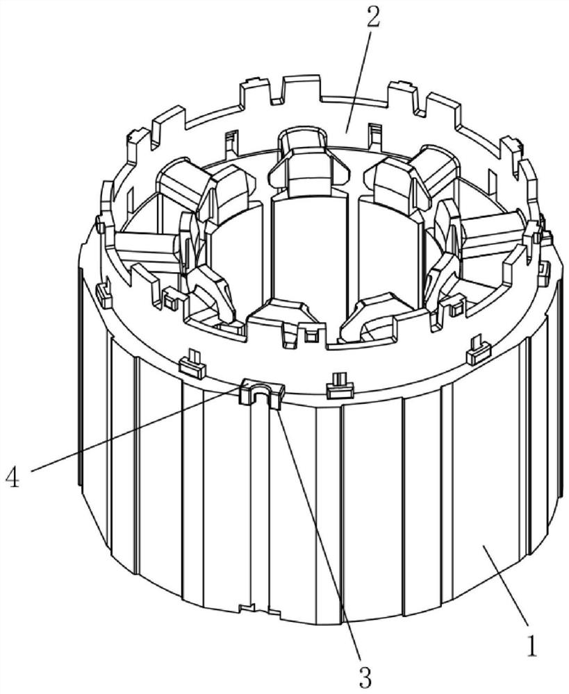
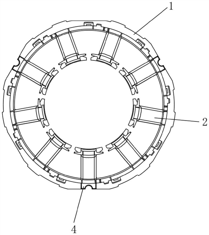
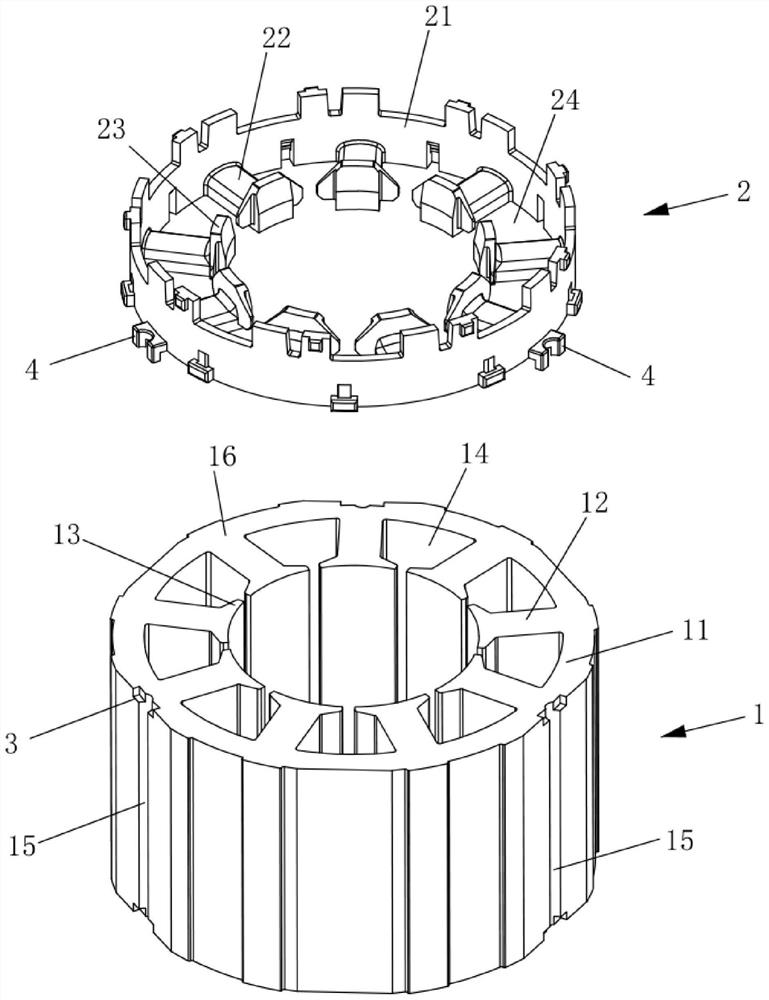
The invention discloses a motor stator and a motor, and belongs to the technical field of motors. The motor stator comprises a stator iron core and an insulation framework; the stator iron core is provided with an iron core end face; the insulation framework is provided with a framework end face; and backflow grooves are formed in the periphery of the stator iron core. The motor stator further comprises a connecting structure. The connecting structure comprises connecting grooves, wherein the connecting grooves are formed in one axial end of the backflow grooves along the peripheral edge of the stator iron core, one ends of the connecting grooves are communicated with the end face of the iron core, and the other ends of the connecting grooves are communicated with the backflow grooves; and connecting protrusions arranged in a protruding mode outwards along the peripheral edge of the insulation framework and protruding out of the framework end face in the axial direction of the insulation framework, wherein avoiding grooves penetrating through the connecting protrusions are formed in the periphery of the connecting protrusions in the axial direction of the insulation framework, the connecting protrusions can be clamped into the connecting grooves to achieve matching, and the avoiding grooves can communicate with the backflow grooves. The stator core and the insulation framework can be stably fixed, circulation of the backflow grooves is not blocked, and the performance of the motor is guaranteed.

Description

technical field [0001] The invention relates to the technical field of motors, in particular to a motor stator and a motor. Background technique [0002] In order to reduce the size of the motor and increase the power, it is desired to increase the slot fill factor of the stator winding. Usually, a circular groove is provided on the end face of the tooth part of the stator core, the end face of the yoke part, or the end face of the connection between the tooth part and the yoke part (that is, the tooth root part). Shaped protrusions, through the fitting of grooves and protrusions, the insulating frame is fixed on the stator core. This prevents deflection of the stator core and insulating frame. [0003] However, this fixed form has the following disadvantages: [0004] 1) There is at most one groove for fixing the insulating frame on the end face of the stator core on each toothed unit of the stator core. In order to minimize the loss of magnetic flux, the groove is too s...

Claims


Application Information

Patent Timeline
Patent Type & Authority Applications(China)
IPC IPC(8): H02K1/18H02K1/20
CPCH02K1/18H02K1/20H02K2213/03
Inventor 徐启剑章玉琳徐峰
Owner SUZHOU AICHI TECH CO LTD
Learn More