
Locomotive braking system electric pneumatic control unit with standardized module

A brake system and control unit technology, applied in the direction of brakes, pneumatic brakes, brake transmissions, etc., can solve problems such as inconsistent hardware composition, failure to realize one-key no fire, and damage to measuring points, so as to save operations and avoid failures Effect

Active Publication Date: 2021-06-22
CRRC QINGDAO SIFANG ROLLING STOCK RES INST +1
View PDF4 Cites 2 Cited by
  • Summary
  • Abstract
  • Description
  • Claims
  • Application Information

AI Technical Summary

Problems solved by technology

[0003] 1. The hardware composition of each module of the electro-pneumatic control unit is completely inconsistent, and the core intelligent modules such as the train management control module, brake cylinder control module and backup control module cannot be interchanged. There are deficiencies in maintainability and other aspects, which is not conducive to Later inspection and maintenance of locomotive operating units;
[0004] 2. At present, the locomotive brake systems at home and abroad have not realized the function of "one-button no-fire", that is, all brake systems need to operate two or more buttons or plugs to realize the setting of the locomotive no-fire mode. Weaknesses in usability;
[0005] 3. The air circuit board of the electro-pneumatic control unit is equipped with multiple air cylinders such as the working air cylinder and the functional air cylinder. When the electro-pneumatic control unit is integrated into the brake cabinet, the position of the air cylinder will be between the electro-pneumatic control Between the unit integrated air circuit board and the air pipeline of the brake cabinet, when there are many pipelines and the air cylinder leaks air, or because the maintenance space at the rear of the electro-pneumatic control unit is small after the brake system is installed, it is difficult to replace the air cylinder. There are deficiencies in maintainability, etc.;
[0006] 4. The pressure measuring points of the electro-pneumatic control unit are arranged on each module, located on the outermost side of the electro-pneumatic control unit, which may easily cause damage to the measuring points during application and transportation

Method used


Image

  • Locomotive braking system electric pneumatic control unit with standardized module
  • Locomotive braking system electric pneumatic control unit with standardized module
  • Locomotive braking system electric pneumatic control unit with standardized module

Examples


Embodiment Construction

[0042] In order to make the purpose, technical solution and advantages of the present application clearer, the present application will be described and explained below in conjunction with the accompanying drawings and embodiments. It should be understood that the specific embodiments described here are only used to explain the present application, and are not intended to limit the present application. Based on the embodiments provided in the present application, all other embodiments obtained by persons of ordinary skill in the art without creative efforts shall fall within the protection scope of the present application.

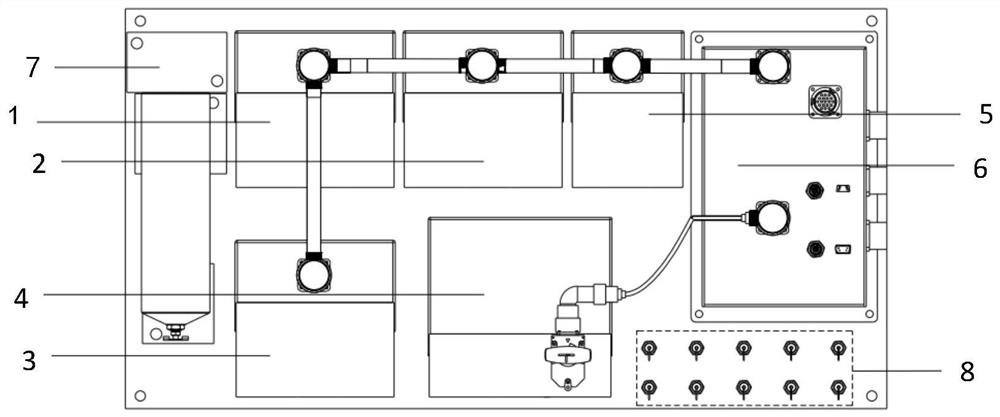
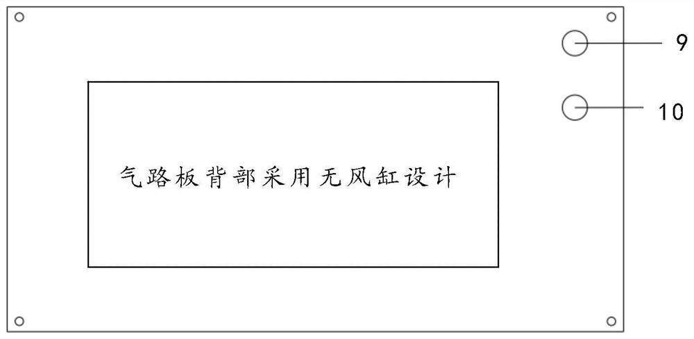
[0043] refer to figure 1 and figure 2 As shown, the electro-pneumatic control unit of the locomotive brake system includes: train pipe control module 1, brake cylinder control module 2, backup control module 3, air brake valve module 4, auxiliary function module 5, electrical interface module 6, filter 7. Integrated air circuit board, concentrated area ...


PUM


Abstract

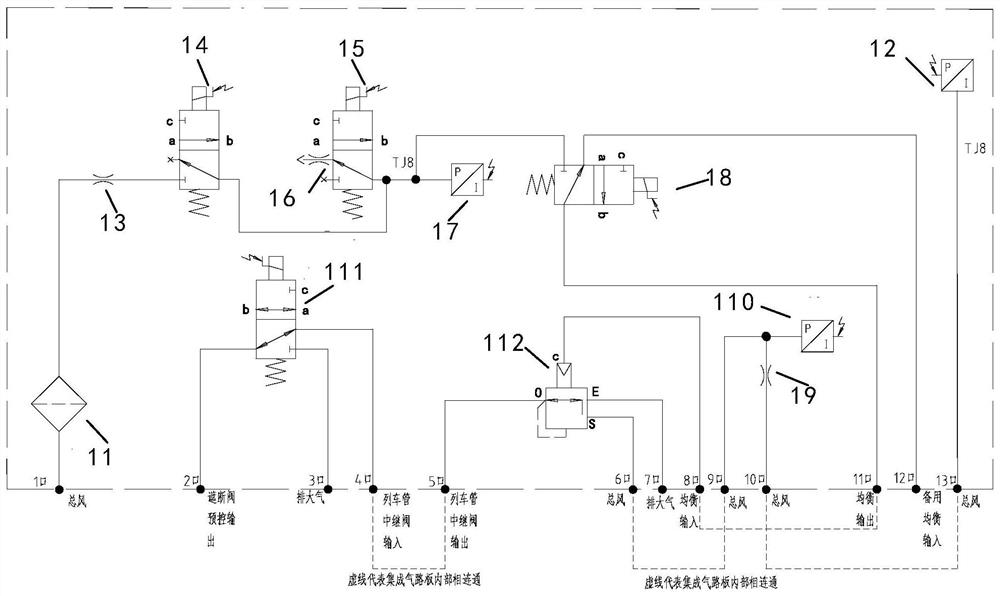
The invention discloses a locomotive brake system electric pneumatic control unit with a standardized module. The control unit comprises a train pipe control module, a brake cylinder control module, a standby control module, an air brake valve module, an auxiliary function module, an electrical interface module, a filter and an integrated gas circuit board. The train pipe control module, the brake cylinder control module and the standby control module are three core intelligent standardization modules of the electric pneumatic control unit; the hardware composition and the internal gas circuit principle of the three modules are completely consistent, and the three modules are composed of pneumatic valve type components and electronic control board cards which are completely identical. The electro-pneumatic control unit is convenient to overhaul and maintain in the later period due to the structural composition; when the locomotive is subjected to fireless return setting, the one-key fireless function is realized, so that the operation is saved, and the efficiency is improved; a rear air cylinder is removed, so that the problem that the air cylinder is difficult to replace is solved; and each pressure measuring point is prevented from being damaged in application and transportation processes.

Description

technical field [0001] The invention relates to the technical field of locomotive braking control. More specifically, the present invention relates to an electro-pneumatic control unit of a locomotive brake system with standardized modules. Background technique [0002] The locomotive brake control system is one of the most important components of the locomotive, which is related to the travel safety of the locomotive, vehicles and passengers. The electro-pneumatic control unit is the core component of the locomotive brake control system, which can execute the instructions of the brake controller, brake display screen or other related systems of the locomotive to achieve the braking function requirements. At present, the most mainstream locomotive braking systems in the world are mainly German Knorr-Bremse CCBⅡ braking system, Faiveley's Eurotrol braking system and domestic CAB-A and CAB-B braking systems. These types of locomotive braking systems The electro-pneumatic con...

Claims


Application Information

Patent Timeline
Patent Type & Authority Applications(China)
IPC IPC(8): B60T8/17B60T13/68B61H11/06B61H11/10
CPCB60T8/1705B60T13/683B61H11/06B61H11/10
Inventor 夏军王令军任向杰吕枭侯化安朱冠汶张茂松苟海鹏
Owner CRRC QINGDAO SIFANG ROLLING STOCK RES INST
Learn More