
Automatic rotary feeding device

A technology of automatic rotation and rotation motor, which is applied in the direction of conveyor control device, transportation and packaging, conveyor objects, etc. It can solve the problems of low efficiency and inability to realize fully automated production, and achieve the effect of improving feeding efficiency

Inactive Publication Date: 2021-06-22
SHANGHAI BRANCH FUZHOU GAOYI COMM CO LTD
View PDF0 Cites 1 Cited by
  • Summary
  • Abstract
  • Description
  • Claims
  • Application Information

AI Technical Summary

Problems solved by technology

[0002] In the production process of existing products, there are still a large number of manual feeding methods, manual feeding is labor-intensive, low in efficiency, and it is impossible to realize fully automated production.

Method used


Image

  • Automatic rotary feeding device
  • Automatic rotary feeding device

Examples


Embodiment Construction

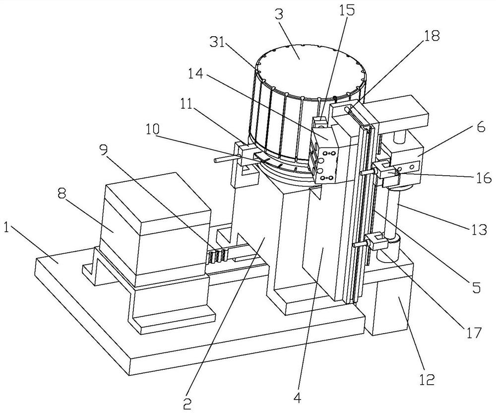
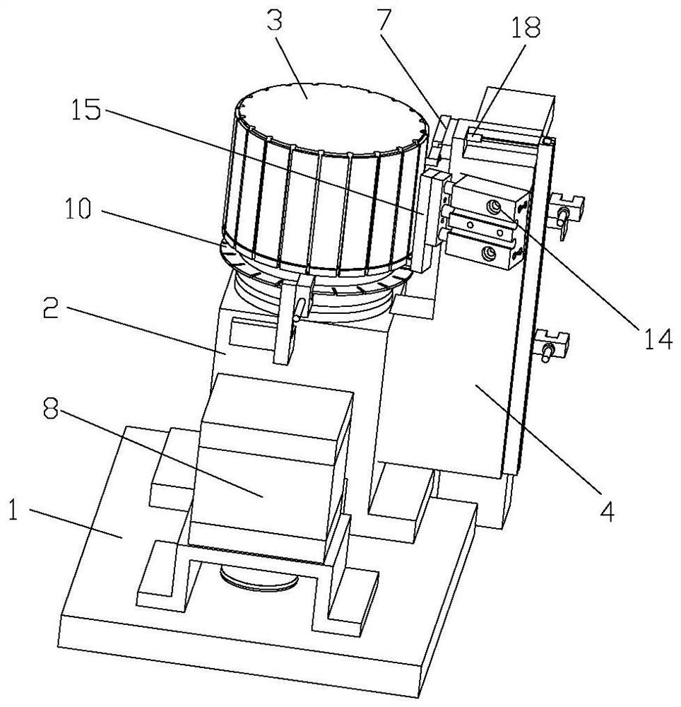
[0016] Such as Figure 1-2 As shown, an automatic rotary feeding device of the present invention comprises a bottom plate 1, a fixed frame 2 is fixed on one side of the upper end surface of the bottom plate 1, and a cylindrical feed bin 3 is rotatably connected to the fixed frame 2, and the feed bin 3 Driven by the rotary drive mechanism to rotate intermittently in the horizontal plane, the periphery of the silo 3 is provided with a plurality of troughs 31 arranged axially along the circumference; the side of the fixed frame 2 is fixed with a bracket 4, A guide rail 5 arranged vertically is fixed on the support 4, and a lifting seat 6 is slid on the guide rail 5, and the lifting seat 6 is driven by a lifting drive mechanism to perform intermittent lifting movements. There is a driving rod 7, and the end of the driving rod 7 extends into the material chute 31 at the upper material level, and the lifting seat 6 drives the driving rod 7 to rise intermittently, so that the materia...


PUM


Abstract

The invention discloses an automatic rotary feeding device which comprises a bottom plate, wherein a fixing frame is fixed to one side of the upper end face of the bottom plate, a cylindrical stock bin is rotationally connected to the fixing frame and driven by a rotary driving mechanism to intermittently rotate in the horizontal plane, and a plurality of feed grooves formed in the axial direction of the stock bin are formed in the periphery of the stock bin in the circumferential direction; a support is fixed to the disc side of the fixing frame, a guide rail arranged in the vertical direction is fixed to the support, a lifting seat is connected to the guide rail in a sliding mode, the lifting seat is driven by a lifting driving mechanism to perform intermittent lifting motion, a shifting rod is fixed to the lifting seat, the end of the shifting rod extends into the feed groove located in a feeding position, and the lifting seat drives the shifting rod to rise intermittently, so that the materials in the feed grooves are ejected out one by one. According to the automatic rotary feeding device, uninterrupted automatic feeding can be achieved, and the feeding efficiency of the materials is greatly improved.

Description

technical field [0001] The invention relates to the field of feeding devices, in particular to an automatic rotating feeding device. Background technique [0002] In the production process of existing products, there are still a large number of manual feeding methods, which are labor-intensive, low in efficiency, and cannot realize fully automated production. Contents of the invention [0003] The object of the present invention is to provide an efficient automatic rotary feeding device. [0004] To achieve the above object, the present invention adopts the following technical solutions: [0005] An automatic rotary feeding device, which includes a bottom plate, a fixed frame is fixed on one side of the end surface of the bottom plate, and a cylindrical material bin is rotatably connected to the fixed frame. Rotating, the periphery of the silo is provided with a plurality of feed troughs arranged axially along the circumferential direction; a bracket is fixed on the disk...

Claims


Application Information

Patent Timeline
Patent Type & Authority Applications(China)
IPC IPC(8): B65G47/12B65G47/82B65G43/08
CPCB65G43/08B65G47/12B65G47/82
Inventor 谢永红刘浩王晓斌
Owner SHANGHAI BRANCH FUZHOU GAOYI COMM CO LTD
Learn More