L-shaped oil drum lifting tool
A spreader and oil drum technology, applied in the direction of load hanging components, transportation and packaging, can solve problems such as hidden safety hazards and inability to turn oil drums more conveniently, so as to achieve a smooth lifting process and simple and convenient turning of oil drums. Effect
- Summary
- Abstract
- Description
- Claims
- Application Information
AI Technical Summary
Problems solved by technology
Method used
Image
Examples
Embodiment 1
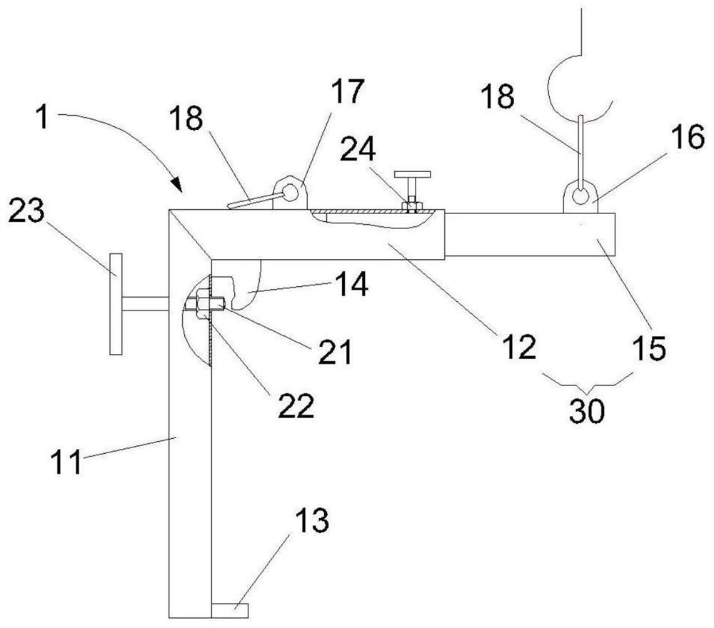
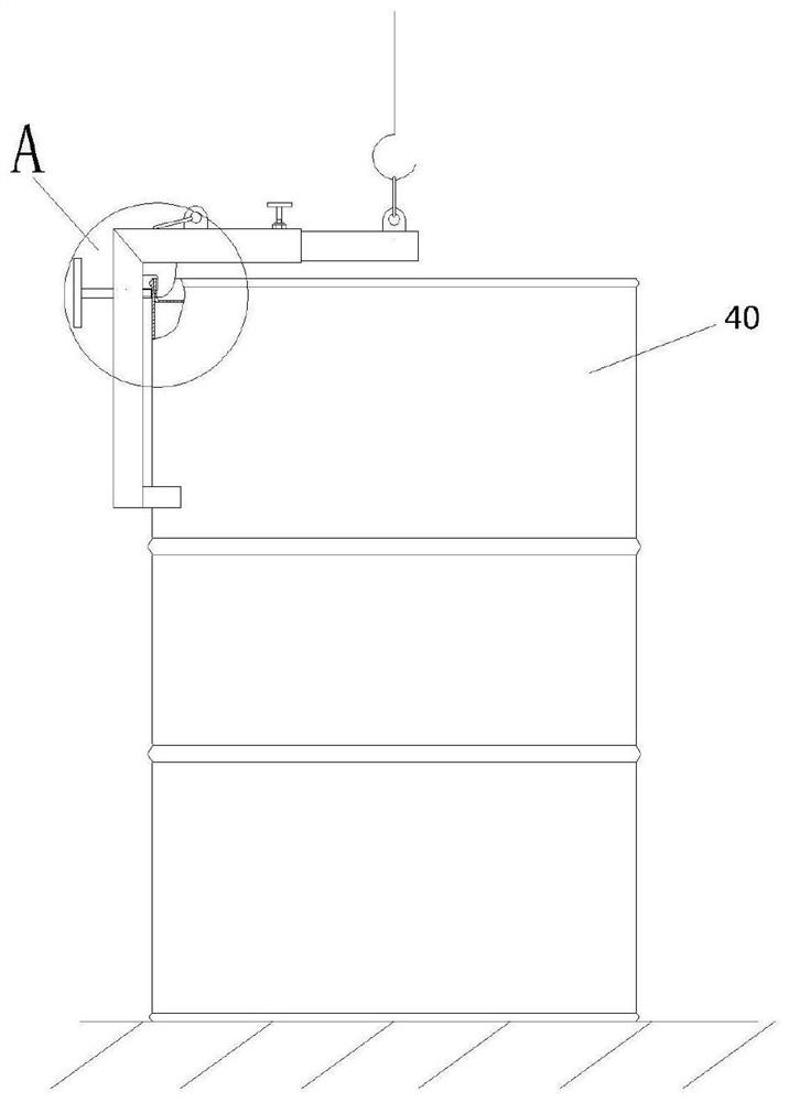
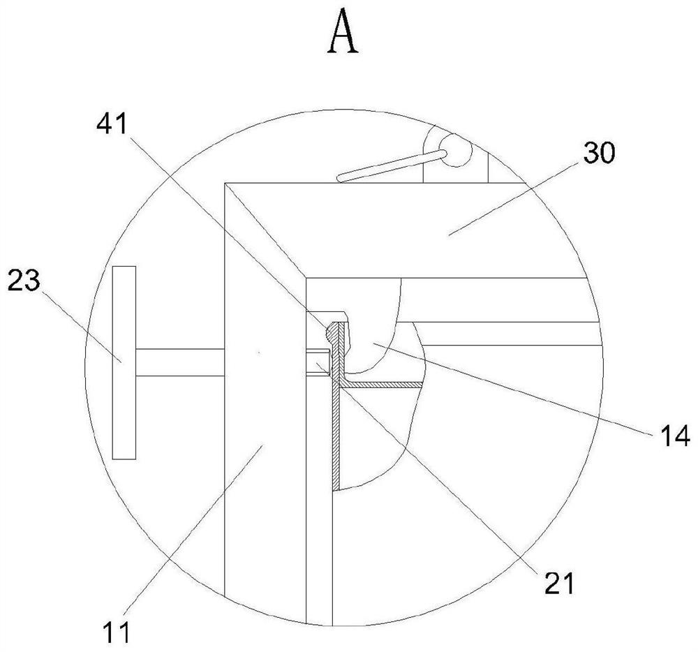
[0025] Such as Figure 1 to Figure 3 As shown, the L-shaped oil drum spreader of the present invention includes an "L"-shaped spreader body 1 composed of a support arm 11 and a boom 30. The support arm 11 and the boom 30 can be made of square pipes, round pipes or other pipe fittings. In this way, the ends where the support arm 11 and the boom 30 are connected are vertically welded and fixed. Furthermore, the support arm 11 and the boom 30 can also be fixed by cutting oblique 45-degree notches at the connected ends and welding to ensure the stability of the spreader in the process of hoisting the oil drum. In this embodiment, the "L"-shaped corner of the "L"-shaped spreader body 1 is provided with an olecranon hook 14, and the olecranon hook 14 is welded to the bottom surface of the boom 30 and the upper part of the support arm 11 respectively. side. The inner side of the lower part of the support arm 11 is provided with a circular arc supporting plate 13, and its upper part...
Embodiment 2
[0027] Figure 1 to Figure 5 As shown, on the basis of Embodiment 1, in order to allow the oil drum 40 to be turned over during hoisting, the upper part of the other side of the boom 30 away from the lifting lug 16 is provided with a turning lug 17, on which the turning lug 17 A lifting ring 18 may further be provided. When the upright oil drum needs to be turned over and placed horizontally, after the spreader is fixed on the oil drum 40 by means of Embodiment 1, as Figure 4 and Figure 5 As shown, the lifting ring 18 on the turning lug 17 is hung on the hook of the crown block and the oil drum 40 is slowly lifted. Due to the setting position of the turning lug 17, the oil drum 40 will slowly tilt during the hoisting process. When the oil drum When only a small part of the bottom of the 40 touches the ground (that is, when the bottom of the oil drum is in point contact with the ground), push the oil drum 40 to the direction to be tilted by manpower, and then control the ho...
Embodiment 3
[0029] Such as Figure 1 to Figure 3 As shown, on the basis of Embodiment 1 or 2, the boom 30 includes a boom fixing section 12 and a boom telescopic section 15 telescopically arranged inside the outer port of the boom fixing section 12, and the boom telescoping Section 15 fits into the inner side of the outer port of the boom fixing section 12 through a small gap, and is telescopically fixed on the boom fixing section 12 by setting set screws 24, so that when the spreader lifts oil drums 40 of different sizes, By adjusting the telescopic section 12 of the boom, the lifting lug 16 is positioned on the axis of the oil drum 40 to meet the requirements for lifting oil drums 40 of different sizes. When this embodiment is based on Embodiment 2, the lifting lug 16 and the flipping lifting lug 17 are respectively arranged on the outer upper part of the boom telescopic section 15 and the inner upper part of the boom fixed section 12, so as to meet the needs of lifting and transporting...
PUM
 Abstract
Description
Claims
Application Information
 - R&D
- Intellectual Property
- Life Sciences
- Materials
- Tech Scout
- Unparalleled Data Quality
- Higher Quality Content
- 60% Fewer Hallucinations
Browse by: Latest US Patents, China's latest patents, Technical Efficacy Thesaurus, Application Domain, Technology Topic, Popular Technical Reports.
© 2025 PatSnap. All rights reserved.Legal|Privacy policy|Modern Slavery Act Transparency Statement|Sitemap|About US| Contact US: help@patsnap.com


