A mechanical support device with self-balancing function

A mechanical support and self-balancing technology, applied in the field of mechanical equipment, can solve the problems of poor efficiency of mechanical device body balance, inability to play the role of base buffer balance, poor effect of base buffer balance, etc., and achieve the effect of improving the protection effect.

Active Publication Date: 2022-04-22
TIANJIN VOCATIONAL INST
View PDF15 Cites 0 Cited by
  • Summary
  • Abstract
  • Description
  • Claims
  • Application Information

AI Technical Summary

Problems solved by technology

[0003] When the mechanical device body of the prior art is installed on the support base, the work of the mechanical device body often drives the support base to perform bumpy motions to varying degrees in the working state. Although the support base of the prior art can support the mechanical device The bumps and vibrations generated by the main body can be buffered and damped to a certain extent, but the efficiency of making the balance between the main body of the mechanical device and the base is poor. The reason is that the four supporting legs at the bottom of the support base are individually cushioned. When the body of the mechanical device bumps and vibrates in a certain direction or at a certain bottom corner of the support base, the support legs at the bottom corner of the support base perform separate buffer and pressure relief work, while the support legs at other positions at the bottom of the support base Then the buffering and balancing effect of the base on this matter is relatively poor, and even the buffering and balancing effect on the base cannot be achieved, which causes the supporting base to fail to self-balance and stabilize the mechanical device body and itself. After buffering and releasing pressure, the mechanical device body and supporting base can reach a stable state, but the working efficiency of the supporting base is greatly limited

Method used


Image

  • A mechanical support device with self-balancing function
  • A mechanical support device with self-balancing function
  • A mechanical support device with self-balancing function

Examples


Embodiment Construction

[0039] The following will clearly and completely describe the technical solutions in the embodiments of the present invention with reference to the accompanying drawings in the embodiments of the present invention. Obviously, the described embodiments are only some, not all, embodiments of the present invention. Based on the embodiments of the present invention, all other embodiments obtained by persons of ordinary skill in the art without making creative efforts belong to the protection scope of the present invention.

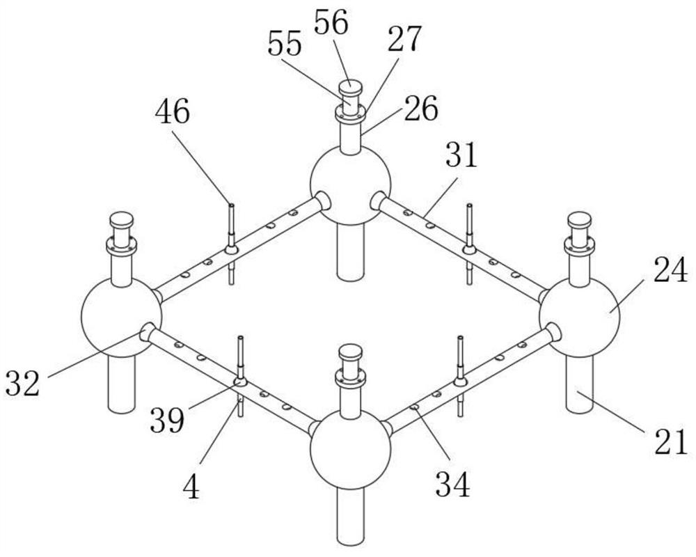
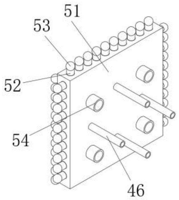
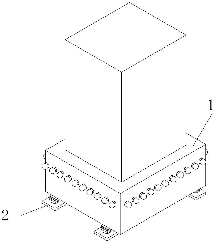
[0040] see Figure 1-11 , the present invention provides a technical solution: a mechanical support device with self-balancing function, including a base 1, the base 1 is a rectangular body, the top of the base 1 is provided with a rectangular slot 11, and the mechanical body is placed in the slot 11 , the bottom of the base 1 is provided with four sets of support mechanisms 2, and the four sets of support mechanisms 2 are mutually symmetrical, the support mec...


PUM


Abstract

The invention relates to the technical field of mechanical equipment, and discloses a mechanical supporting equipment with self-balancing function, which includes a base, a rectangular slot is opened on the top of the base, four sets of supporting mechanisms are arranged on the bottom of the base, and the supporting mechanisms include supporting columns, Four sets of supporting columns are respectively arranged at four right angles at the bottom of the base. The mechanical support device with self-balancing function, the present invention sets the support mechanism, the bottom end of the balance ball is set by the support column, the support spring and the bottom plate, the bottom plate is set on the ground so that the base and the mechanical body can be stable, and the top of the balance ball is set by setting The buffer column, the limit plate and the limit spring, under the joint elastic force of the limit spring and the support spring, enable the four sets of balance balls to be stably arranged in the corresponding balance chambers, and then two adjacent balance balls pass through the balance bar With a stable connection, the further stabilized balance ball enables the bottom plate to maintain the overall stability of the base.

Description

technical field [0001] The invention relates to the technical field of mechanical equipment, in particular to a mechanical support equipment with a self-balancing function. Background technique [0002] There are many types of mechanical equipment. When the mechanical equipment is running, some of its parts and even itself can perform different forms of mechanical movement. The mechanical equipment consists of a driving device, a transmission device, a transmission device, a working device, a braking device, a protective device, a lubrication system, and a cooling system. system and other components. [0003] When the mechanical device body of the prior art is installed on the support base, the work of the mechanical device body often drives the support base to perform bumpy motions to varying degrees in the working state. Although the support base of the prior art can support the mechanical device The bumps and vibrations generated by the main body can be buffered and damp...

Claims


Application Information

Patent Timeline
Patent Type & Authority Patents(China)
IPC IPC(8): F16F15/02F16M5/00F16F15/023F16F15/04F25D31/00
CPCF16M5/00F16F15/022F16F15/023F16F15/04F16F15/046F25D31/00
Inventor 张云秀何四平霍淑珍郑树展
Owner TIANJIN VOCATIONAL INST
Why Eureka
Try Eureka