Eureka AIR delivers breakthrough ideas for toughest innovation challenges, trusted by R&D personnel around the world.

Accurately-controlled illuminating lamp movement adjusting device

A mobile adjustment and precise control technology, which is applied in the direction of lighting devices, lighting auxiliary devices, lighting device components, etc., can solve the problems of inability to change the irradiation position, narrow irradiation range, and non-movable adjustment of lighting lamps, so as to achieve flexible irradiation positions accurate effect

Inactive Publication Date: 2021-06-22
WUCHANG UNIV OF TECH
View PDF3 Cites 0 Cited by
  • Summary
  • Abstract
  • Description
  • Claims
  • Application Information

AI Technical Summary

Problems solved by technology

[0004] Most of the existing lighting lamps are non-movable and adjustable, and only have lighting function. The switch of the lighting lamp is realized only by the operator pressing the switch, or the adjustment is made in a small range through the swing angle. Since such lighting equipment is fixed Working in a certain position leads to a narrow irradiation range, and the irradiation position cannot be flexibly changed according to actual needs, which affects the lighting effect

Method used


Image

  • Accurately-controlled illuminating lamp movement adjusting device
  • Accurately-controlled illuminating lamp movement adjusting device
  • Accurately-controlled illuminating lamp movement adjusting device

Examples


Embodiment Construction

[0033] The present invention will be further described through specific embodiments below in conjunction with the accompanying drawings.

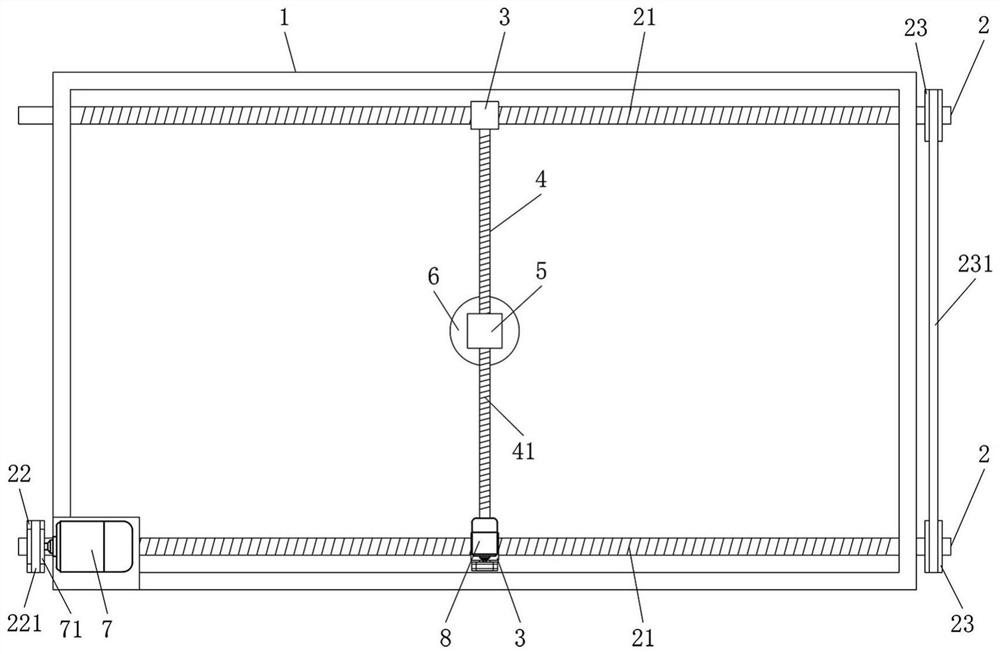
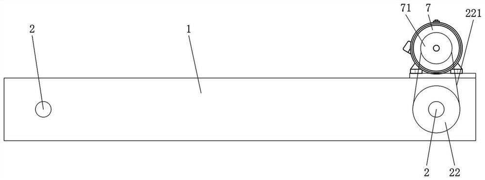
[0034] Such as figure 1 , Figure 4 , a precise control device for adjusting the movement of lighting lamps, including a rectangular mounting frame 1, parallel horizontal driving rods 2 are respectively installed on the inner sides of the two long sides of the mounting frame 1, and lateral moving blocks are respectively installed on the lateral driving rods 2 3. A longitudinal drive rod 4 is connected between the lateral movement blocks 3, a longitudinal movement block 5 is mounted on the longitudinal drive rod 4, and a dome light 6 is installed below the longitudinal movement block 5, and the dome light 6 is located between the transverse drive rod 2 and the longitudinal drive rod 4. Adjust the position under drive.

[0035] Thus, the lateral driving rod 2 can drive the lateral moving block 3 to move laterally, thereby driving the longit...


PUM


Abstract

The invention provides an accurately-controlled illuminating lamp movement adjusting device, and relates to the technical field of stage equipment. The accurately-controlled illuminating lamp movement adjusting device comprises a rectangular mounting rack, wherein parallel transverse driving rods are arranged on the inner sides of the two long side edges of the mounting rack respectively, and transverse moving blocks are arranged on the transverse driving rods respectively; a longitudinal driving rod is connected between the transverse moving blocks, and a longitudinal moving block is arranged on the longitudinal driving rod; a ceiling lamp is arranged below the longitudinal moving block; and the position of the ceiling lamp is adjusted under the driving action of the transverse driving rods and the longitudinal driving rod. According to the accurately-controlled illuminating lamp movement adjusting device, the transverse driving rods are adopted to drive the transverse moving blocks to transversely move so as to drive the longitudinal driving rod to transversely move, the longitudinal driving rod is adopted to drive the longitudinal moving block to longitudinally move, and therefore transverse and longitudinal movement of the ceiling lamp arranged on the longitudinal moving block is achieved. Thus, the irradiation position of an illuminating lamp can be flexibly and accurately changed.

Description

technical field [0001] The present invention relates to the technical field of precise control, more [0002] Generally speaking, it relates to a precisely controlled lighting lamp movement adjustment device. Background technique [0003] In large factories or open-air environments, when nighttime work is required, lights are required for auxiliary operations. With the advancement of technology and the improvement of users' living standards, machine control is becoming more and more intelligent, and lighting lights are also proposed. New requirements, hope that lighting can be more intelligent. The intelligence of lighting is mainly manifested in the control of lighting. [0004] Most of the existing lighting lamps are non-movable and adjustable, and only have lighting function. The switch of the lighting lamp is realized only by the operator pressing the switch, or the adjustment is made in a small range through the swing angle. Since such lighting equipment is fixed Wor...

Claims


Application Information

Patent Timeline
Patent Type & Authority Applications(China)
IPC IPC(8): F21V21/15
CPCF21V21/15
Inventor 安庆原菊蒲李凤旭
Owner WUCHANG UNIV OF TECH
Why Eureka
Eureka Blog
Learn More