Laser cutting device for metal cutting

A laser cutting and metal cutting technology, applied in laser welding equipment, metal processing equipment, welding equipment, etc., can solve problems such as excessive energy, lower production efficiency of the assembly line, non-replaceable condenser lens, etc., and achieve the effect of improving production efficiency

Inactive Publication Date: 2019-02-15
YANGZHOU HANGFEI PRECISION ELECTROMECHANICAL CO LTD
View PDF0 Cites 0 Cited by
  • Summary
  • Abstract
  • Description
  • Claims
  • Application Information

AI Technical Summary

Problems solved by technology

[0002] The laser has the characteristics of good parallelism and high energy. It is often used in the field of cutting and processing. The laser cutting machine used now often places a condenser lens in front of the light source system to focus the parallel laser light generated by the light source system into one point. Because of this The energy of the focus point is extremely high, so the focus is used for cutting and processing, but the condenser lens of the existing laser cutting machine cannot be replaced, and the cutting energy required for different metal cutting parts is different, and the energy is too large or too small. To achieve a good cutting effect, it is difficult to meet the demand only by changing the intensity of the light source
[0003] However, most assembly lines, including metal material laminating lines, can only be fixedly configured on the assembly line when configuring laser cutting machines, due to limitations of weight, structure and other factors. When the material reaches the position of the laser cutting machine, it is necessary to stop the movement of the assembly line so that the material can be stopped so that it can be cut easily. Cutting cannot achieve continuous feeding

Method used


Image

  • Laser cutting device for metal cutting

Examples


Embodiment Construction

[0009] The preferred embodiments of the present invention will be described in detail below in conjunction with the accompanying drawings, so that the advantages and features of the present invention can be more easily understood by those skilled in the art, so as to define the protection scope of the present invention more clearly.

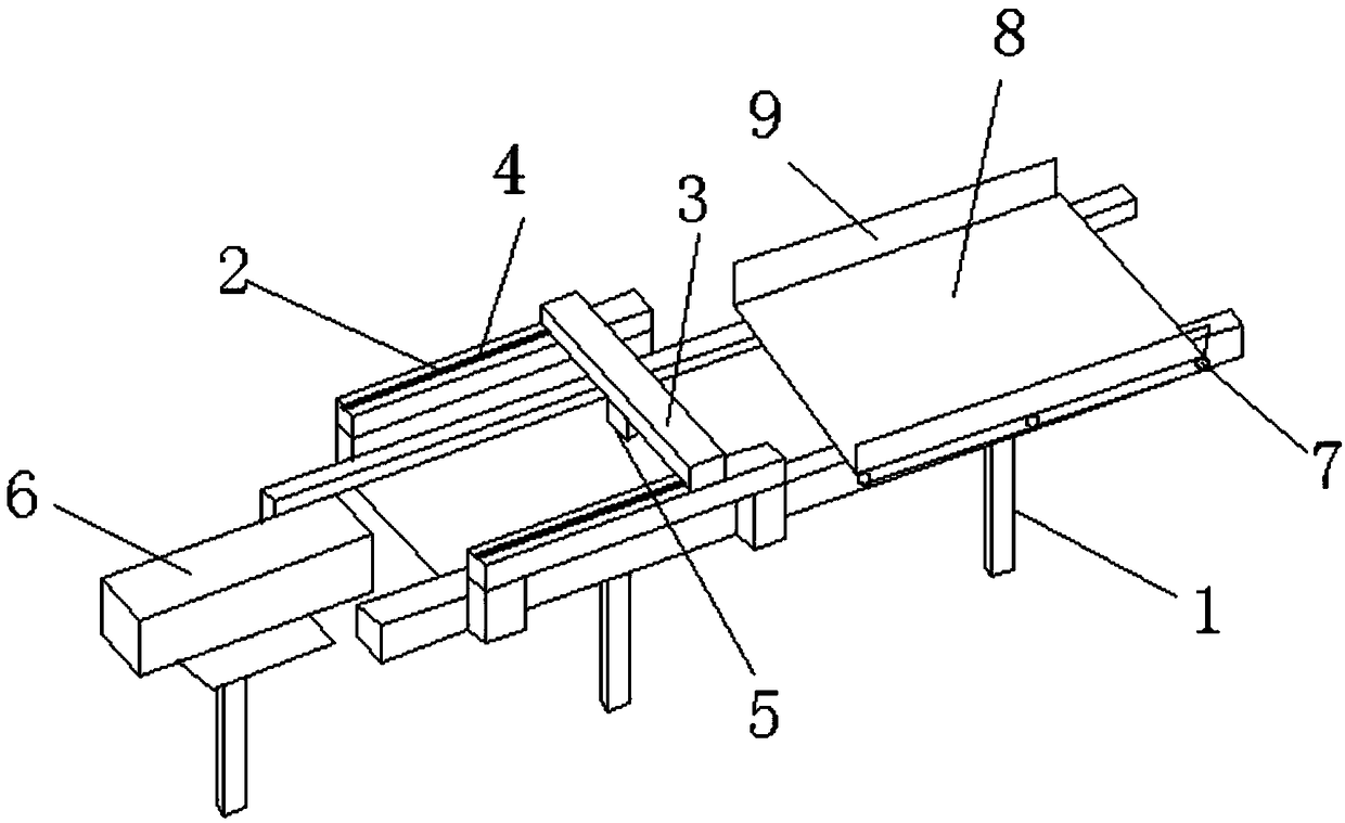
[0010] Such as figure 1 Shown is a laser cutting device for metal cutting, comprising a support 1, a transverse support 2 and a longitudinal support 3 arranged on the support 1, the transverse support 2 is arranged on both ends of the support 1, and the transverse support 2 slideway 4 is provided at the top of the horizontal support 2, a longitudinal support 3 is provided in the slideway 4 of the transverse support 2, and a focusing field lens 5 is arranged at the bottom of the longitudinal support 3, and the focusing field lens 5 can move along the longitudinal support. The two ends of the support are arranged on the transverse bracket through t...


PUM


Abstract

The invention relates to a laser cutting device for metal cutting. The laser cutting device comprises a support, transverse supports arranged on the support and a longitudinal support. The longitudinal support is arranged in slideways of the transverse supports. The bottom end of the longitudinal support is provided with a focusing field lens. The focusing field lens can move along the longitudinal support. The two ends of the longitudinal support are fixedly arranged on the transverse supports through fixed columns. A laser device is arranged on one side of the focusing field lens. A conveying device is arranged on the other side of the focusing field lens. The conveying device comprises conveying rollers and a conveyor belt arranged on the conveying rollers. The two sides of the conveyorbelt are provided with limiting plates for preventing parts to be cut from falling off. The longitudinal support moves along the transverse supports to drive the focusing field lens to move. The focusing field lens can move on the longitudinal support. The longitudinal support moves up and down along the fixed columns to drive the focusing field lens to move up and down. Accordingly, omni-directional movement of the focusing field lens in the height, longitudinal and transverse directions is realized so that an output laser beam can conduct cutting in multiple dimensionality directions of a material.

Description

technical field [0001] The invention relates to a laser cutting device, in particular to a laser cutting device for metal cutting. Background technique [0002] The laser has the characteristics of good parallelism and high energy. It is often used in the field of cutting and processing. The laser cutting machine used now often places a condenser lens in front of the light source system to focus the parallel laser light generated by the light source system into one point. Because of this The energy of the focus point is extremely high, so the focus is used for cutting and processing, but the condenser lens of the existing laser cutting machine cannot be replaced, and the cutting energy required for different metal cutting parts is different, and the energy is too large or too small. To achieve a good cutting effect, it is difficult to meet the demand only by changing the intensity of the light source. [0003] However, most assembly lines, including metal material laminatin...

Claims


Application Information

Patent Timeline
Patent Type & Authority Applications(China)
IPC IPC(8): B23K26/08
CPCB23K26/08
Inventor 蒋睿徐凯川
Owner YANGZHOU HANGFEI PRECISION ELECTROMECHANICAL CO LTD
Why Eureka
Try Eureka