Edge cutting device of furniture filler and using method of edge cutting device

A technology for fillers and furniture, applied in the direction of metal processing, etc., can solve the problems that the trimmer cannot meet the requirements, consume a lot of time, and the trimmer does not have it.

Pending Publication Date: 2020-04-17
海南科技职业大学
View PDF10 Cites 0 Cited by
  • Summary
  • Abstract
  • Description
  • Claims
  • Application Information

AI Technical Summary

Problems solved by technology

[0003] The existing trimming machine adopts the traditional trimming machine form, and there are many inconveniences in the trimming process of fillers. For example, the blade of the trimming machine is fixedly installed, and the filler can only move in one direction. When changing the trimming direction It is necessary to pick up the filler and fix it again, and it will take a lot of time to cut the next time. For example, the cutting edge can only be carried out along a straight line. For some cutting edges that require arcs, the existing edge cutting machine cannot meet the requirements. , additional trimming is required manually, and some leftovers from trimming can be recycled and reused. Most of the existing trimming machines do not have this function

Method used


Image

  • Edge cutting device of furniture filler and using method of edge cutting device
  • Edge cutting device of furniture filler and using method of edge cutting device
  • Edge cutting device of furniture filler and using method of edge cutting device

Examples


Embodiment Construction

[0028] The following will clearly and completely describe the technical solutions in the embodiments of the present invention with reference to the accompanying drawings in the embodiments of the present invention. Obviously, the described embodiments are only some, not all, embodiments of the present invention. Based on the embodiments of the present invention, all other embodiments obtained by persons of ordinary skill in the art without making creative efforts belong to the protection scope of the present invention.

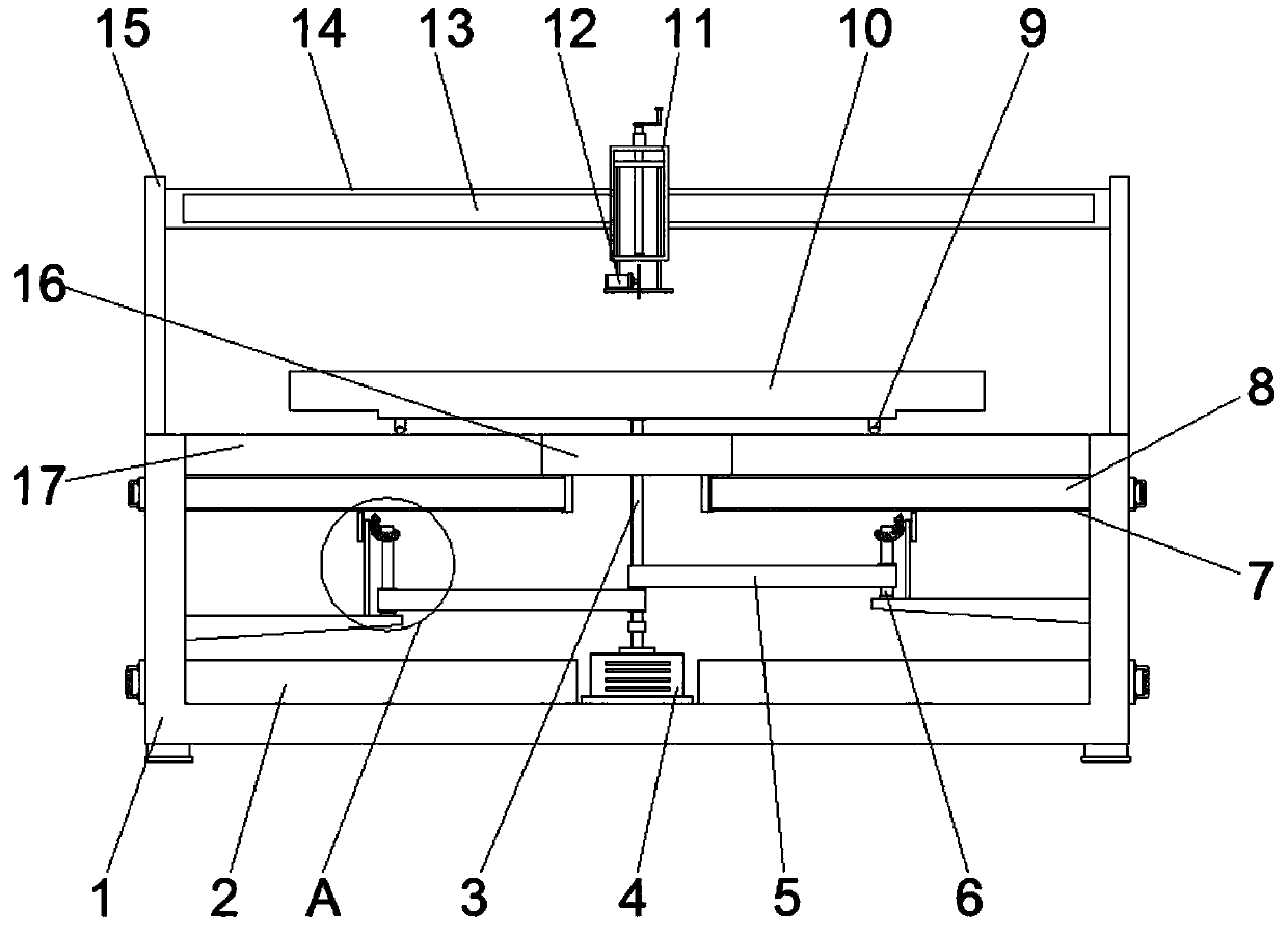
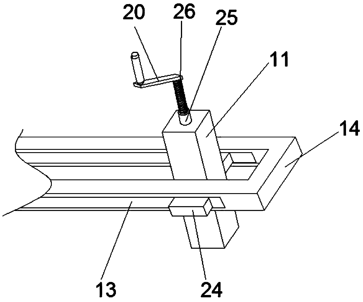
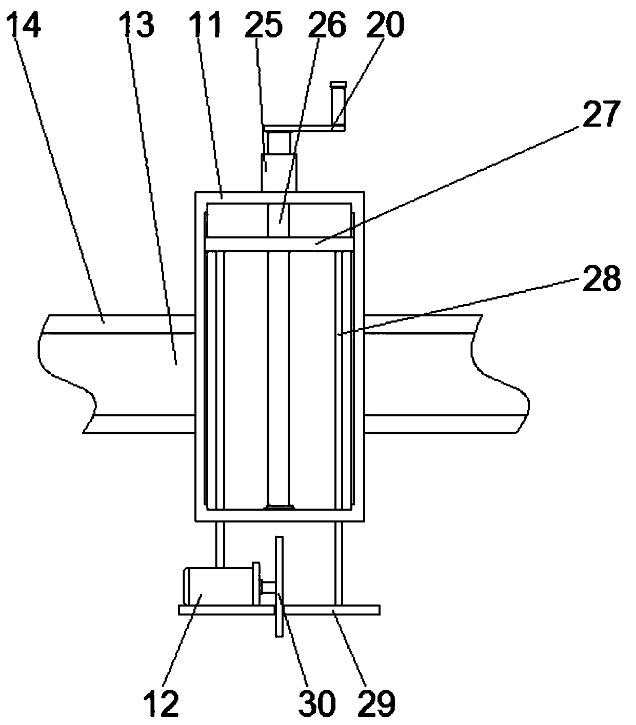
[0029] see Figure 1~5 , in an embodiment of the present invention, an edge trimming device for a furniture filling and a method for using the same, includes a housing 1, the housing 1 is a cuboid with an open top surface and a circular plate 16 is arranged at the center of the opening, and the circular plate 16 is The peripheral surface of the plate 16 is fixedly connected to one end of a plurality of connecting rods 17, and the plurality of connecting rods 1...


PUM


Abstract

The invention discloses an edge cutting device of a furniture filler and a using method of the edge cutting device, and relates to the technical field of furniture related equipment. The edge cuttingdevice specifically comprises a shell, wherein the shell is a cuboid with an opening in the top surface, a circular plate is arranged in the center of the opening of the shell, the circumferential surface of the circular plate is fixedly connected with one ends of a plurality of connecting rods, an annular groove is in rolling connection with balls, the balls are in rolling connection in rolling grooves formed in the bottom ends of fixing blocks, the top ends of the fixing blocks are fixedly connected with corresponding positions of the lower surface of the workbench, supporting plates are fixedly connected to the two sides of the upper surface of the shell, and fixing plates are fixedly connected between the opposite surfaces of the tops of the two supporting plates. According to the edgecutting device, a mounting plate can be lifted in a certain range, so that the distance between a blade and the workbench can be adjusted, the furniture filling with different thicknesses can be cutto a certain extent, the filler can be cut in the arc and the linear direction, and meanwhile, cut leftover materials can be recycled and reused.

Description

technical field [0001] The invention relates to the technical field of furniture-related equipment, in particular to a trimming device for furniture fillings and a method for using the same. Background technique [0002] Sofas, recliners, etc. are commonly used furniture in people's lives. In order to maintain softness and improve comfort, these furniture often need to be filled with cloth, elastic cotton, etc. as fillers. Due to the variety of furniture forms and shapes, the furniture filling needs to be trimmed to make it suitable for the structure of the furniture. Usually, edge cutting machines are used to trim and trim the filling. [0003] The existing trimming machine adopts the traditional trimming machine form, and there are many inconveniences in the trimming process of fillers. For example, the blade of the trimming machine is fixedly installed, and the filler can only move in one direction. When changing the trimming direction It is necessary to pick up the fill...

Claims


Application Information

Patent Timeline
Patent Type & Authority Applications(China)
IPC IPC(8): B26D1/18B26D5/02B26D7/26B26D7/18B26D7/20
CPCB26D1/18B26D5/02B26D7/2635B26D7/18B26D7/20B26D2007/0018
Inventor 张娜
Owner 海南科技职业大学
Why Eureka
Try Eureka