Clamping equipment for composite mechanical material processing

A clamping equipment and material processing technology, which is applied in the direction of manipulators, chucks, manufacturing tools, etc., can solve the problems of leaving marks on the plate and lack of processing methods, and achieve the effect of plate protection

Pending Publication Date: 2022-01-28
YANCHENG INST OF TECH +1
View PDF0 Cites 0 Cited by
  • Summary
  • Abstract
  • Description
  • Claims
  • Application Information

AI Technical Summary

Problems solved by technology

[0004] The purpose of the present invention is to provide a clamping device for composite mechanical material processing, which solves the problem that the existing method for clamping composite mechanical plates is relatively simple, and the method of direct

Method used


Image

  • Clamping equipment for composite mechanical material processing
  • Clamping equipment for composite mechanical material processing
  • Clamping equipment for composite mechanical material processing

Examples


Embodiment 1

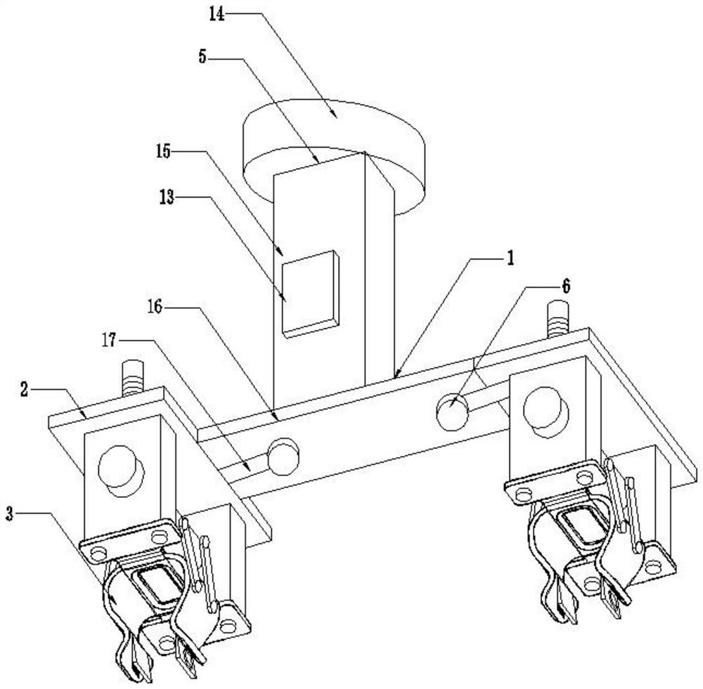
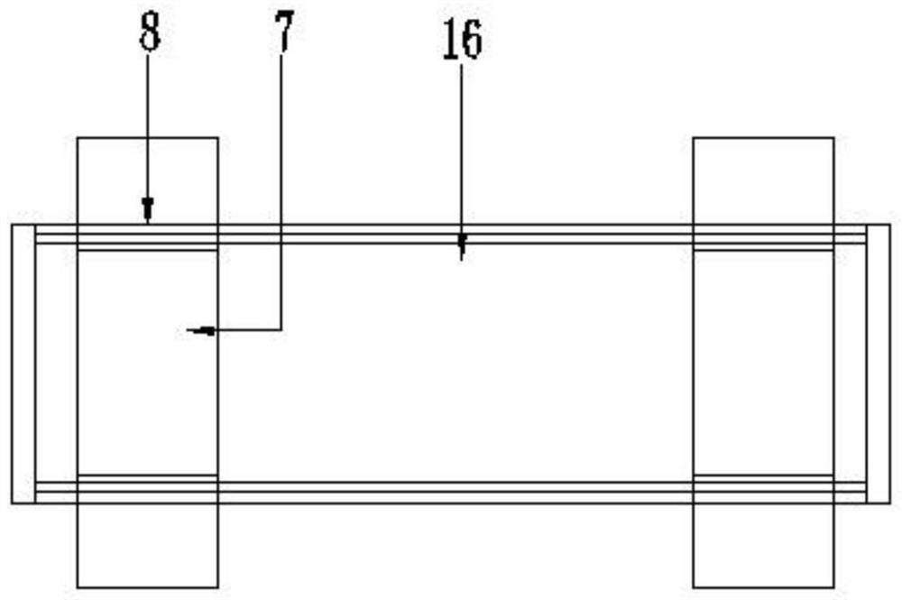
[0022] Example 1: See Figure 1-5 , the present invention provides a technical solution: a clamping device for processing composite mechanical materials, including a plate clamping device, the plate clamping device includes a bidirectional drive mechanism 1, an installation base 2, a clamping driver 3 and a clamping piece 4, The two-way driving mechanism 1 is composed of a longitudinal driver 5 and a transverse driver 6. The lower end of the longitudinal driver 5 is connected to the transverse driver 6. The installation base 2 is divided into two groups and is symmetrically installed on the two ends of the transverse driver 6. The installation base 2 includes a central opening. The main board 8 with guide port 7 and two groups of side plates 9 symmetrically installed on the lower end of the main board 8, the clamping driver is installed between the two groups of side plates 9, the power output end of the clamping drive is connected with the clamping piece 4, and the clamping T...

Embodiment 2

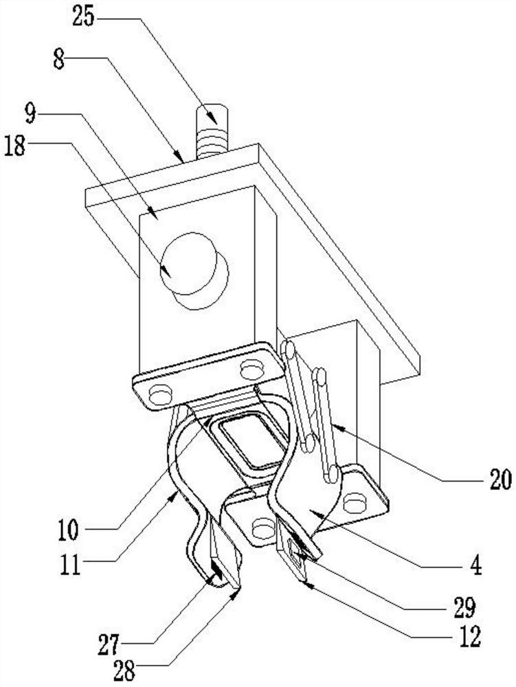
[0025] Embodiment 2: as Figure 4 As shown: the clamping driver is composed of a main shaft 18, a movable half ring 19, a driving rod 20 and a driving mechanism. The two ends of the main shaft 18 are fixedly connected with two groups of side plates 9. Pulley 21, two groups of movable semi-rings 19 are symmetrically installed on the outside of main shaft 18, pulley 21 is slidably embedded on the main shaft 18, the lower end of driving rod 20 is connected with clamping piece 4 and the upper end is connected with movable semi-ring 19, two Also be provided with connecting rod 22 between group drive rod 20, the outer end of connecting rod 22 is connected with driving mechanism, and driving mechanism is installed on the mainboard 8, and movable half ring 19 carries out activity regulation along main shaft 18.

Embodiment 3

[0026] Embodiment 3: as Figure 4 As shown: the driving mechanism is composed of a driving motor 23, a driving wheel 24, a screw 25 and a movable disc 26, the power output end of the driving motor 23 is connected to the driving wheel 24, the driving wheel 24 is meshed with the screw 25, and the screw 25 is inserted into the main board 8 and the outer end is connected with the movable disk 26, the movable disk 26 is connected with the drive rod 20 in rotation, the driving motor 23 drives the driving wheel 24 to rotate, the driving wheel 24 promotes the rotation of the screw rod 25, the screw rod 25 moves longitudinally and drives the movable disk to rotate, and the During the up-and-down adjustment of the disc, the connecting rod 22 is used to push the movable half-ring 19 to adjust, and the movable half-ring 19 is used to push the driving rod 20 to be displaced, and the purpose of adjusting the splint 11 is achieved by using the displacement.

[0027] further improved, such as...


PUM


Abstract

The invention discloses clamping equipment for composite mechanical material processing. The clamping equipment comprises a plate clamping device, the plate clamping device comprises a bidirectional driving mechanism, mounting pedestals, clamping drivers and clamping sheets; the bidirectional driving mechanism is composed of a longitudinal driver and a transverse driver; the lower end of the longitudinal driver is connected with the transverse driver; the two sets of mounting pedestals are symmetrically mounted at the two ends of the transverse driver; each mounting pedestal comprises a main plate with a guide opening formed in the middle and two sets of side plates symmetrically mounted at the lower end of the main plate, and one clamping driver is mounted between the two sets of side plates; the power output end of each clamping driver is connected with the corresponding clamping sheet; and each clamping piece comprises a bottom plate located in the middle and two sets of clamping plates movably installed on the two sides of the bottom plate. According to the clamping equipment of the invention, an automatic driving mode is adopted, the purpose of soft contact with a plate can be achieved, and the use safety and the automation degree of the clamping equipment are improved.

Description

technical field [0001] The invention relates to the technical field of clamping equipment, in particular to a clamping equipment for processing composite mechanical materials. Background technique [0002] A gripper is a device that holds an object to manipulate it. It is able to grip and loosen objects while performing certain actions. Motion equipment often mimics the movement of the human body, and in the case of grippers, the movement of fingers. The "fingers" themselves are not grippers, they are just special custom tools used to grip objects, called "grips", the most widely used gripper is the pneumatic gripper; it is essentially a Air powered cylinder. When air is supplied, the gripper jaws will approach the object and hold it firmly for other manipulations, and when the direction of the air changes, the gripper will release the object. The typical application is to change the direction of the object or move the object during the selection and placement operation....

Claims


Application Information

Patent Timeline
IPC IPC(8): B25J15/06B65G47/90
CPCB25J15/06B65G47/90
Inventor 王如刚郭乃宏孔祥晔刘晛方忠庆
Owner YANCHENG INST OF TECH
Why Eureka
Try Eureka