Optimized jack contact element, composite hole sleeve structure and manufacturing method of optimized jack contact element and composite hole sleeve structure

A technology of jack contacts and composite holes, applied in the direction of contact parts, etc., can solve the problems of increased yield force, large deformation, and small cross-sectional area of ​​contacts, and achieves large conductive cross-sectional area, reduced weight, and large load. Effect

Pending Publication Date: 2021-06-22
深圳先启能源技术有限公司
View PDF3 Cites 0 Cited by
  • Summary
  • Abstract
  • Description
  • Claims
  • Application Information

AI Technical Summary

Problems solved by technology

Considering the life of the high-speed fine stamping die and the stability of the product in the traditional socket contact, the punch of the high-speed fine stamping die should be made as wide as possible (the stiffness of the punch structure is proportional to the width of the punch), resulting in the entire contact piece. If the cross-sectional area is small, the electrical conductivity of the socket contact will be poor; the load of the simply supported beam is proportional to the width of the beam. For the same load, the beam width will be smaller, and the deformation of the beam will be larger. If the deformation is large, the yield force will also change. Larger, the elastic deformation life of the simply supported beam is also shortened, so we propose an optimized socket contact, a composite socket structure, and its manufacturing method to solve the above-mentioned problems

Method used


Image

  • Optimized jack contact element, composite hole sleeve structure and manufacturing method of optimized jack contact element and composite hole sleeve structure
  • Optimized jack contact element, composite hole sleeve structure and manufacturing method of optimized jack contact element and composite hole sleeve structure
  • Optimized jack contact element, composite hole sleeve structure and manufacturing method of optimized jack contact element and composite hole sleeve structure

Examples


Embodiment 1

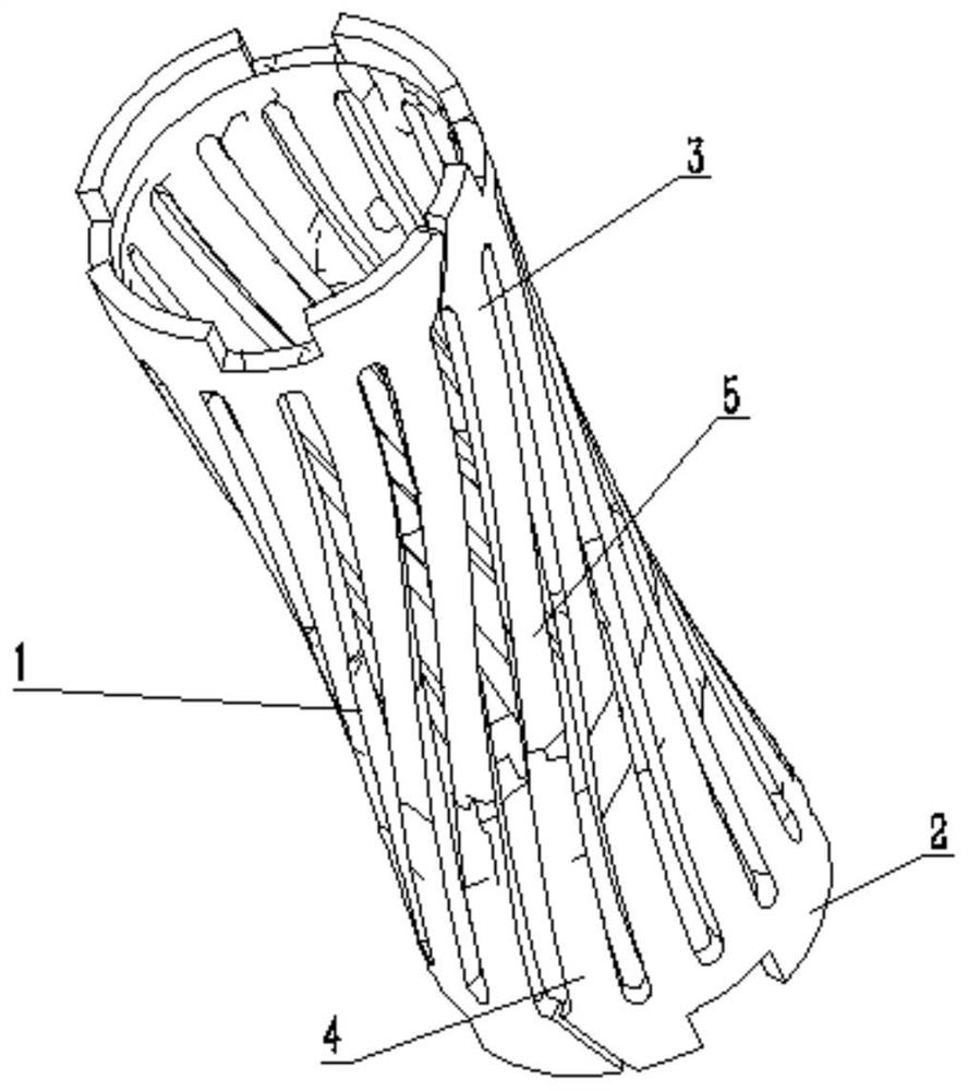
[0043] refer to Figure 1-18 In this embodiment, an optimized socket contact piece is proposed, including a socket contact piece 3, a simple support beam group 5 is included on the socket contact piece 3, and the simple support beam group 5 includes an upper part, a middle part and a lower part respectively, and the upper part The cross-sectional areas of the middle and lower parts are 1-2:1:1-2 respectively, and the top and bottom of the simply supported beam group 5 are fixedly installed with rolled metal sheets.

Embodiment 2

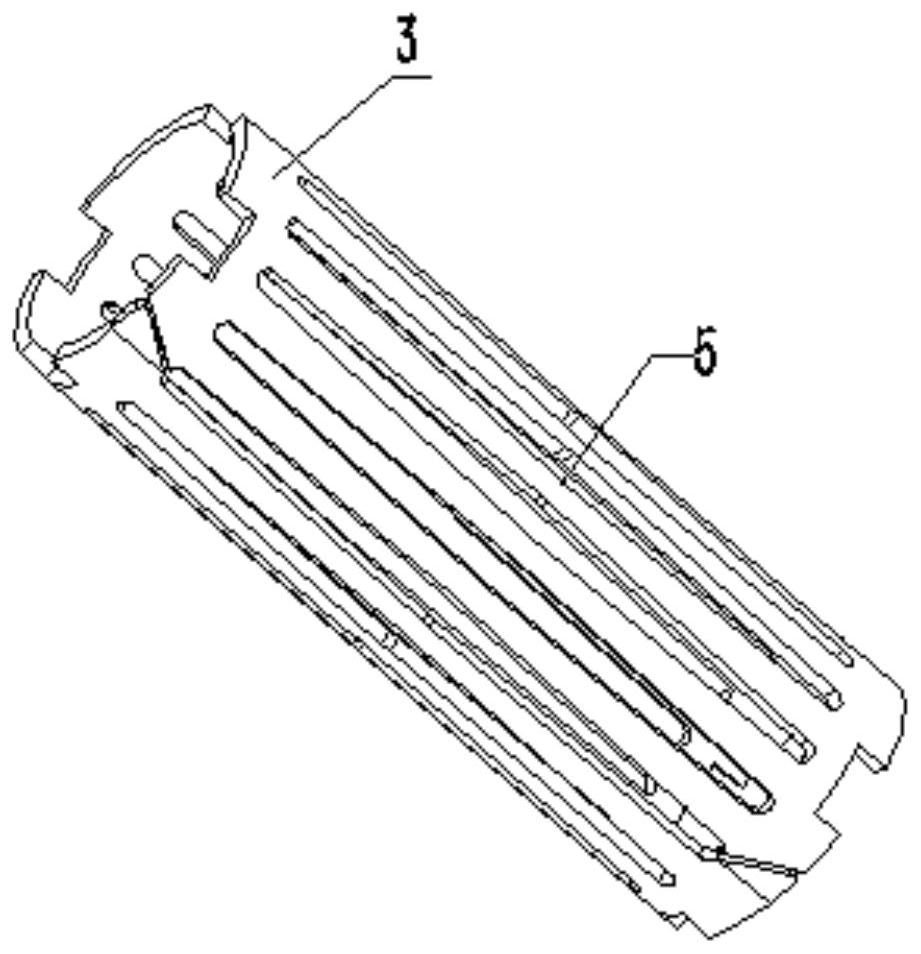
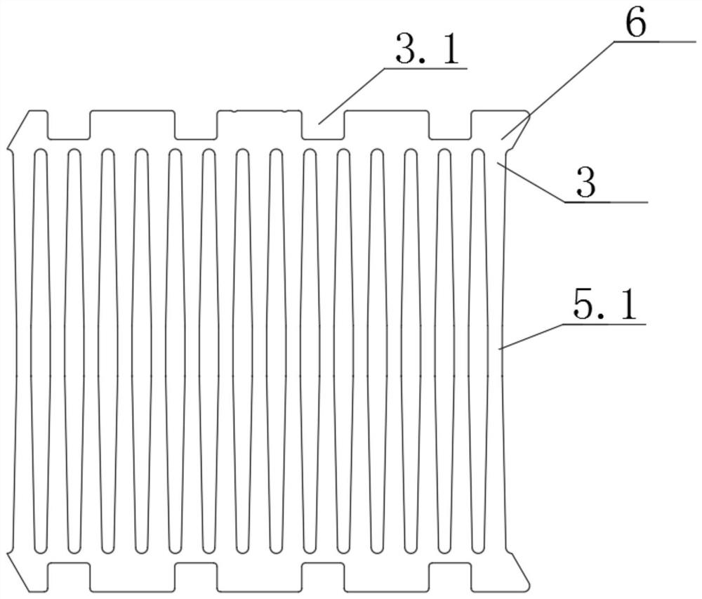
[0045] In this embodiment, in the attached Figure 3-4 Among them, the simply supported beam group 5 includes a plurality of first simply supported beams 5.1, and the first simply supported beams 5.1 respectively include an upper part, a middle part and a lower part, and the cross-sectional areas of the upper part, the middle part and the lower part are respectively 2:1: 1.5. The tops and bottoms of multiple first simply supported beams 5.1 are respectively fixedly connected with two rolled metal sheets. The end surfaces on both sides of the middle part of the first simply supported beams are linear structures, and the end surfaces on both sides of the upper and lower parts are arc-shaped.

Embodiment 3

[0047] In this embodiment, in the attached Figure 5-6 Among them, the simply supported beam group 5 includes a plurality of second simply supported beams 5.2, and the second simply supported beams 5.2 respectively include an upper part, a middle part and a lower part, and the upper and lower parts of the plurality of second simply supported beams 5.2 are respectively connected with two rolls The round metal sheets are fixedly connected, the second simply supported beam 5.2 is a wide upper and lower narrow structure, the end faces on both sides of the second simply supported beam 5.2 are arc-shaped, and the cross-sectional areas of the upper, middle and lower parts are respectively 2:1.2:1 .


PUM


Abstract

The invention belongs to the field of high-current connectors, and particularly relates to an optimized jack contact, a composite hole sleeve structure and a manufacturing method of the optimized jack contact. Aiming at the problems of poor conductivity, poor supporting capability and short service life of the existing jack contact, the invention provides the following scheme: the jack contact comprises a jack contact, and the jack contact comprises a simply supported beam group; the simply supported beam group comprises an upper part, a middle part and a lower part, wherein the cross sectional areas of the upper part, the middle part and the lower part are (1-2): 1: (1-2) respectively, and the top and the bottom of the simply supported beam set are both fixedly provided with edge rolling metal; the simply supported beam set comprises a plurality of first simply supported beams, and each first simply supported beam comprises an upper portion, a middle portion and a lower portion. According to the invention, after the torsion process treatment, the simply supported beam becomes a rotary hyperboloid. The projection of the axial cross section of the spiral cylinder wall is a rotary hyperboloid, the rotary hyperboloid is uniformly distributed in a circle, the conductive sectional area of the contact element is large, the load is large, and the weight of the contact element is reduced.

Description

technical field [0001] The invention relates to the technical field of high-current connectors, in particular to an optimized jack contact, a composite socket structure, and a manufacturing method thereof. Background technique [0002] At this stage, socket contacts are used in the industry, which are designed for traditional processing ideas. Considering the life of the high-speed fine stamping die and the stability of the product in the traditional socket contact, the punch of the high-speed fine stamping die should be made as wide as possible (the stiffness of the punch structure is proportional to the width of the punch), resulting in the entire contact piece. If the cross-sectional area is small, the electrical conductivity of the socket contact will be poor; the load of the simply supported beam is proportional to the width of the beam. For the same load, the beam width will be smaller, and the deformation of the beam will be larger. If the deformation is large, the yi...

Claims


Application Information

Patent Timeline
Patent Type & Authority Applications(China)
IPC IPC(8): H01R13/33H01R13/11
CPCH01R13/33H01R13/11
Inventor 骆忠保
Owner 深圳先启能源技术有限公司
Why Eureka
Try Eureka