
Hairpin

A hair and clip technology, applied in the field of hair clips, can solve problems such as hair pain and unpleasantness, and achieve the effects of excellent hair clips, durable hair clips, and strengthening of bearing lugs

Inactive Publication Date: 2003-12-10
YASUDA KK
View PDF0 Cites 1 Cited by
  • Summary
  • Abstract
  • Description
  • Claims
  • Application Information

AI Technical Summary

Problems solved by technology

In this way, pulling the hair clip B will pull out the hair, which will of course cause pain, and the act of pulling the hair from the head itself will cause a very unpleasant sensation.

Method used


Image

  • Hairpin
  • Hairpin
  • Hairpin

Examples


Embodiment Construction

[0025] In the following, an embodiment of the present invention shown in the drawings will be described.

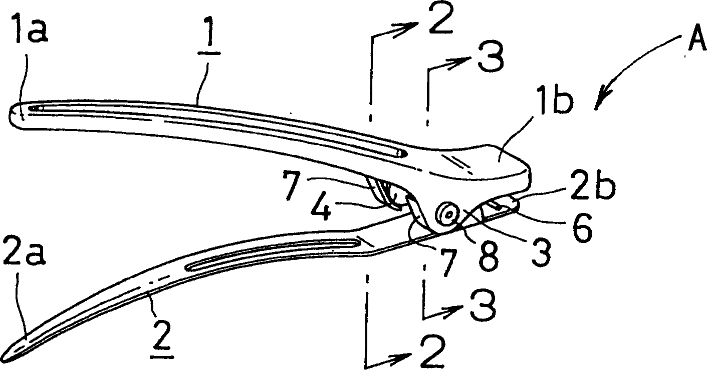
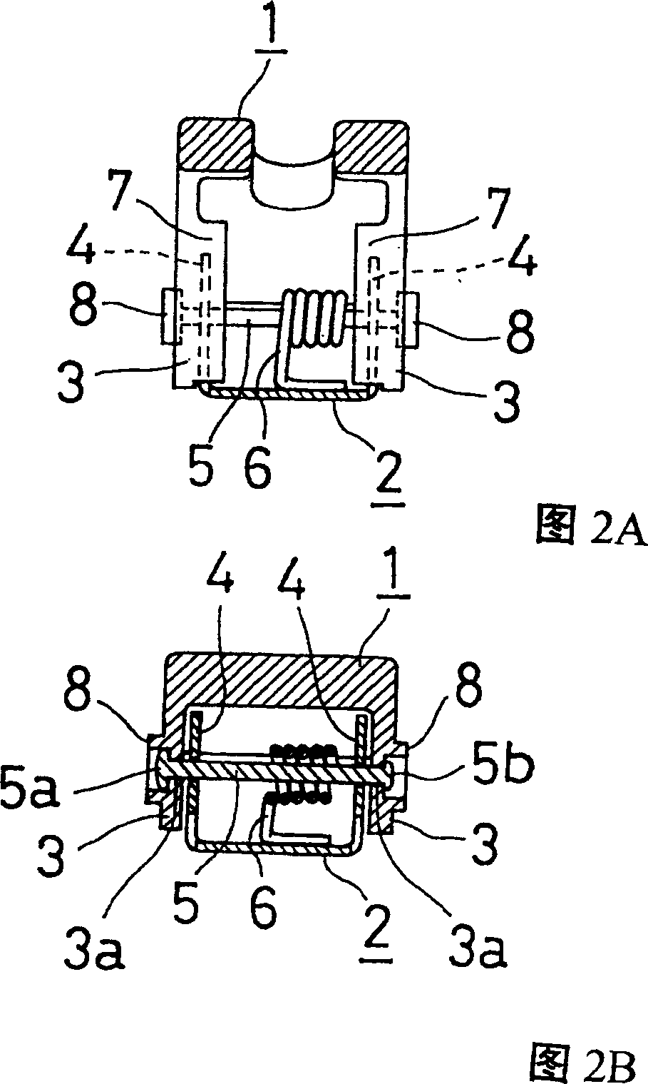
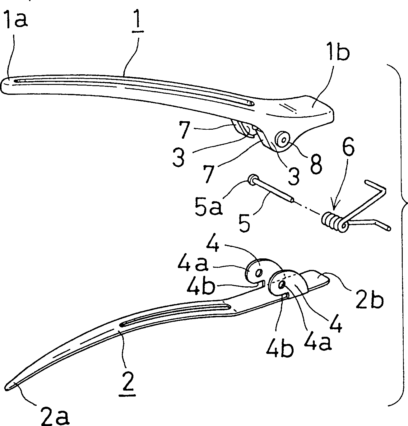
[0026] The hair clip A in the embodiment of the present invention is to combine a pair of clamping pieces 1, 2 formed in the shape of a crane's beak as shown in the figure, on the side of the opening and closing operation parts 1b, 2b at the other end of the length direction, It is formed by elastically biasing one end 1a, 2a of the coil spring 6 wrapped on the pin shaft 5 toward the direction of closing each other in the normal state.

[0027] In the state of being clamped on the hair, the clamping piece 1 located on the outside is made of semi-hard synthetic resin, and on the inner surface of one end of the opening and closing operation part 1b side, there is a certain interval protrudingly arranged towards the opposite side. A pair of bearing lugs 3, 3 protruding from one clamping piece 2. In the center of the bearing lugs 3, 3, there are pin shaft insertion holes 3a,...


PUM


Abstract

To provide a hairclip in which hairs are not entangled in a gap between the bearing projection piece of one pinching piece and the bearing projection piece of the other inching piece, or in a gas between the rivet head or the rivet caulking section of a pivot and the bearing projection piece. A pinching piece positioned outside being attached to the hair and a pinching piece corresponding to the pinching piece are assembled by means of bearing projection pieces provided in the inside thereof. A coil spring is provided around a rivet passed through the bearing projection pieces, and both pinching pieces are urged in the direction of closing. A hair entanglement prevention section is provided in the bearing projection piece positioned outside of the adjacent bearing projection pieces, and a hair entanglement prevention ring projection is provided in the exterior of the peripheral face of the pivoted through-hole.

Description

technical field [0001] The present invention relates to a hair clip for clamping hair by spring force, and mainly relates to a hair clip for temporarily clamping hair during hair styling, make-up and the like. Background technique [0002] Such hairpins in the past, such as Figure 5 and Image 6 As shown, the structure of this known hair clip B is to have a pair of clamping pieces 51, 52, the opening and closing operation parts 51b, 52b sides at one end of the length direction are combined with each other, and the two clamping pieces 51 are connected by means of a spring 56. The other ends of , 52 are biased towards the direction of closing each other in the normal state. [0003] This kind of hair clip B protrudes from the inner surface of one end of the two holding pieces 51, 52 on the side of the opening and closing operation parts 51b, 52b, and protrudes a pair of bearing lugs protruding toward the opposite holding pieces 51, 52. 53, 53, 54, 54, the two clamping piece...

Claims


Application Information

Patent Timeline
Patent Type & Authority Patents(China)
IPC IPC(8): A45D8/00A45D8/20
CPCA45D8/20A45D8/14
Inventor 安田昌弘
Owner YASUDA KK
Learn More