A powder ball milling device that is convenient for discharging
A technology of ball milling and powder, which is applied in the direction of grain processing, etc., can solve cumbersome problems and achieve the effect of convenient discharge
- Summary
- Abstract
- Description
- Claims
- Application Information
AI Technical Summary
Problems solved by technology
Method used
Image
Examples
Embodiment 1
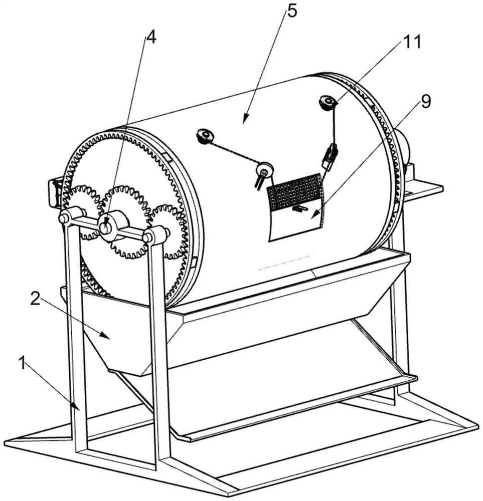
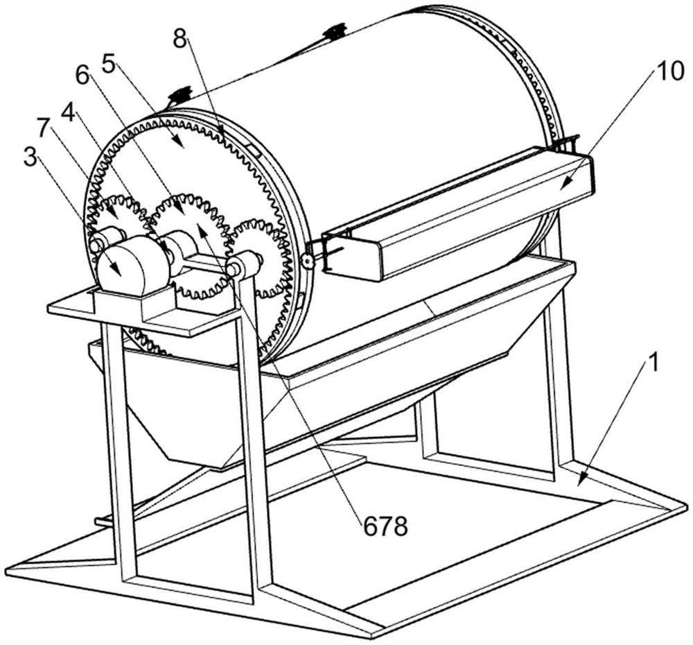
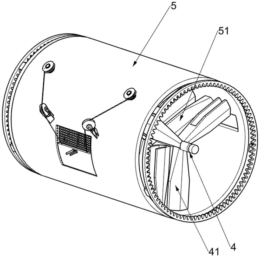
[0026] A powder ball milling device that is easy to discharge, such as Figure 1-9 As shown, it includes a placing frame 1, a collection bucket 2, a servo motor 3, a rotating shaft 4, a toggle wedge 1 41, a roller 5, a toggle wedge 2 51, a power conversion mechanism 678 and a cover opening mechanism 9, the collection bucket 2 is installed in the middle of the placing frame 1, the collecting bucket 2 is used to make the powder after running in to leave the device, the servo motor 3 is installed on the top of one side of the placing frame 1, the servo motor 3 is used to drive the rotating shaft 4 to rotate, and the rotating shaft 4 is fixedly connected On the output shaft of the servo motor 3, the rotating shaft 4 is used to drive the toggle wedge 1 41 and the power gear 6 to rotate, the rotating shaft 4 is rotatably connected with the placing frame 1, and several toggle wedges are evenly distributed and fixed on the rotating shaft 4. Block one 41, the drum 5 is rotatably arrang...
Embodiment 2
[0031] On the basis of Example 1, as Figure 8-9As shown, it also includes a steel ball adjustment mechanism 10, the steel ball adjustment mechanism 10 is arranged on the drum 5, and the steel ball adjustment mechanism 10 is used to adjust the number of steel balls, so that the pure aluminum powder and the pure titanium powder can be more fully run-in Together, the steel ball adjustment mechanism 10 includes a ball storage frame 101, a mounting rod 102, a swing clamp 103, a fixed column 104, a nut 105, a screw 106, a rotating flap 107 and a chuck 108. The ball storage frame 101 is installed on the drum 5. Outside, the ball storage frame 101 is used for holding steel balls, the installation rod 102 is rotatably arranged on the ball storage frame 101, the installation rod 102 is used to support the swing clamp 103 and the device on it, and the two ends of the installation rod 102 are symmetrically rotated. A swing clamp 103 is provided. The swing clamp 103 is used to clamp the c...
Embodiment 3
[0034] On the basis of Example 2, as Figure 5 and Figure 7 As shown in the figure, it also includes a built-in discharge adjustment mechanism 11. The built-in discharge adjustment mechanism 11 is arranged on the drum 5. Through the cooperation of the cover opening mechanism 9 and the built-in discharge adjustment mechanism 11, the run-in powder can be collected into One, to prevent the run-in powder from remaining in the device, the built-in discharge adjustment mechanism 11 includes a fixed seat 111, a directional wheel 112, a rotating shaft 113, a swing baffle 114, a winding wheel 115, a pulling rope 116 and a torsion force Spring 117, a pair of fixed seats 111 are fixed on the outside of the drum 5, the fixed seats 111 are used to support the directional wheel 112, the directional wheel 112 is rotatably provided on the fixed seat 111, and the drum 5 is rotatably provided with a pair of rotating shafts 113, the rotating shaft 113 is used to drive the swinging baffle 114 t...
PUM
 Abstract
Description
Claims
Application Information
 - R&D
- Intellectual Property
- Life Sciences
- Materials
- Tech Scout
- Unparalleled Data Quality
- Higher Quality Content
- 60% Fewer Hallucinations
Browse by: Latest US Patents, China's latest patents, Technical Efficacy Thesaurus, Application Domain, Technology Topic, Popular Technical Reports.
© 2025 PatSnap. All rights reserved.Legal|Privacy policy|Modern Slavery Act Transparency Statement|Sitemap|About US| Contact US: help@patsnap.com


