
Pressure detection assembly and ultrasonic welding equipment

A technology for detecting components and pressure, applied in welding equipment, non-electric welding equipment, metal processing equipment, etc., can solve problems such as easy fluctuation, unfavorable mass production, welding position deviation, etc., to improve welding accuracy, compact overall structure, and welding The effect of accurate position

Active Publication Date: 2021-06-25
GUANGDONG LYRIC ROBOT INTELLIGENT AUTOMATION CO LTD
View PDF4 Cites 2 Cited by
  • Summary
  • Abstract
  • Description
  • Claims
  • Application Information

AI Technical Summary

Problems solved by technology

[0002] In the process of using ultrasonic welding equipment to weld workpieces, it is necessary to strictly control the pressure between the welding head and the workpiece. Generally, the pressure between the welding head and the workpiece is detected by the pressure detection unit to perform ultrasonic welding under a suitable pressure to ensure welding Accuracy; however, when the existing ultrasonic welding equipment is driving the welded part down, there are gaps between the pressure detection unit and the drive part, and between the pressure detection unit and the welded part, which is prone to fluctuations, resulting in deviation of the welding position. It affects welding accuracy and welding quality. At the same time, the gap is uncontrollable and cannot be compensated for each device through the setting program, which is not conducive to mass production

Method used


Image

  • Pressure detection assembly and ultrasonic welding equipment
  • Pressure detection assembly and ultrasonic welding equipment
  • Pressure detection assembly and ultrasonic welding equipment

Examples


Embodiment Construction

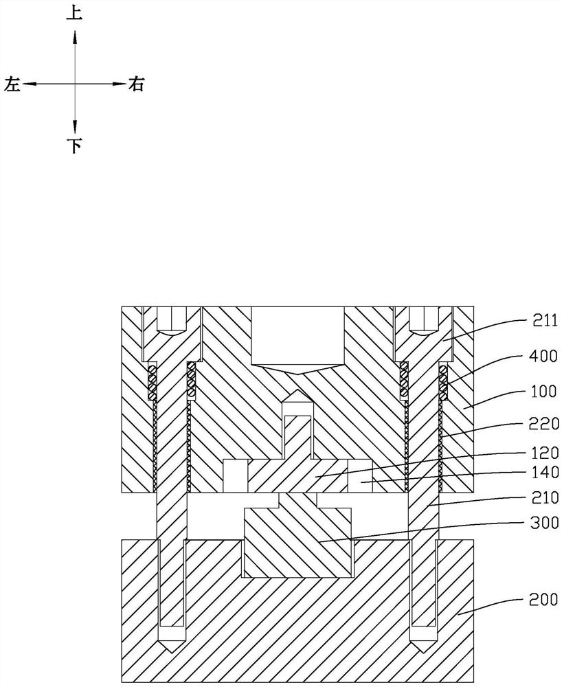
[0035] This part will describe the specific embodiment of the present invention in detail, and the preferred embodiment of the present invention is shown in the accompanying drawings. Each technical feature and overall technical solution of the invention, but it should not be understood as a limitation on the protection scope of the present invention.

[0036] In the description of the present invention, it should be understood that the orientation descriptions, such as up, down, front, back, left, right, etc. indicated orientations or positional relationships are based on the orientations or positional relationships shown in the drawings, and are only In order to facilitate the description of the present invention and simplify the description, it does not indicate or imply that the device or element referred to must have a specific orientation, be constructed and operated in a specific orientation, and thus should not be construed as limiting the present invention.

[0037] I...


PUM


Abstract

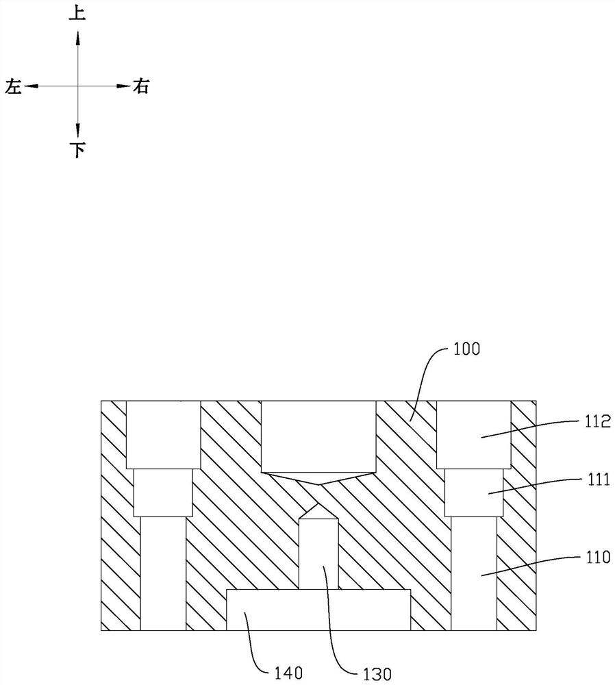
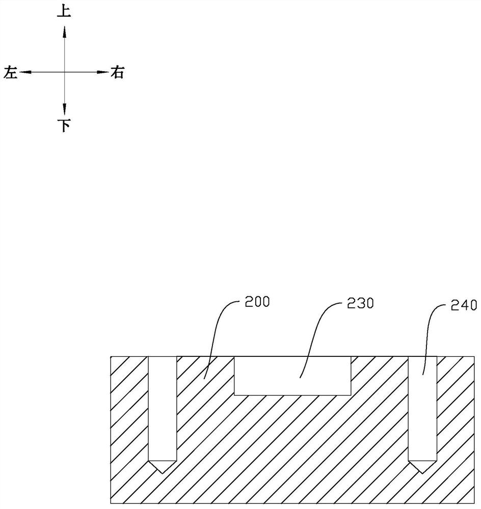
The invention discloses a pressure detection assembly and ultrasonic welding equipment. The pressure detection assembly comprises a first connecting piece, a second connecting piece, a detection unit and an elastic piece, and the first connecting piece is provided with a first guide part; the second connecting piece is connected with the first connecting piece, and the second connecting piece is provided with a second guide part matched with the first guide part; the detection unit is arranged between the first connecting piece and the second connecting piece, and the detection unit is used for collecting a pressure value between the first connecting piece and the second connecting piece; and the elastic piece is connected between the first connecting piece and the second connecting piece, and the elastic piece enables the first connecting piece and the second connecting piece to clamp the detection unit. According to the pressure detection assembly, connection gaps between a pressure detection unit and a driving part and between the pressure detection unit and a welding part can be eliminated, fluctuation is avoided, and the welding precision is effectively improved.

Description

technical field [0001] The invention relates to the technical field of detection units, in particular to pressure detection components and ultrasonic welding equipment. Background technique [0002] In the process of using ultrasonic welding equipment to weld workpieces, it is necessary to strictly control the pressure between the welding head and the workpiece. Generally, the pressure between the welding head and the workpiece is detected by the pressure detection unit to perform ultrasonic welding under a suitable pressure to ensure welding Accuracy; however, when the existing ultrasonic welding equipment is driving the welded part down, there are gaps between the pressure detection unit and the drive part, and between the pressure detection unit and the welded part, which is prone to fluctuations, resulting in deviation of the welding position. It affects the welding accuracy and welding quality. At the same time, the gap is uncontrollable and cannot be compensated for ea...

Claims


Application Information

Patent Timeline
Patent Type & Authority Applications(China)
IPC IPC(8): B29C65/08B29C65/78B23K20/10B23K20/26
CPCB29C65/08B29C65/78B23K20/10B23K20/26B23K31/12
Inventor 杜义贤卢其辉李新华罗剑王俊文黄付延陈德王峰方念徐卓
Owner GUANGDONG LYRIC ROBOT INTELLIGENT AUTOMATION CO LTD
Learn More