Cable winding device for three-way thermoplastic

A winding device and heat-through technology, which is applied in the directions of transportation and packaging, delivery of filamentous materials, thin material processing, etc., can solve problems such as low efficiency, uncontrollable winding distance, unsightly winding of finished pipe fittings, etc. achieve a high degree of automation

Active Publication Date: 2021-06-25
ZHEJIANG SCI-TECH UNIV
View PDF16 Cites 0 Cited by
  • Summary
  • Abstract
  • Description
  • Claims
  • Application Information

AI Technical Summary

Problems solved by technology

The traditional winding process is manual winding. In the era of modern technology development, manual winding has disadvantages such as long time-consuming, low efficiency, uncontrollable winding distance, and unsightly winding of finished pipe fittings.

Method used


Image

  • Cable winding device for three-way thermoplastic
  • Cable winding device for three-way thermoplastic
  • Cable winding device for three-way thermoplastic

Examples


Embodiment 1

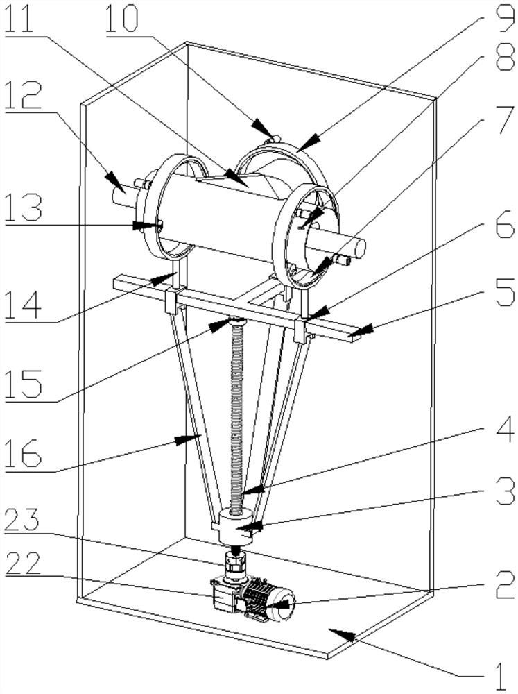
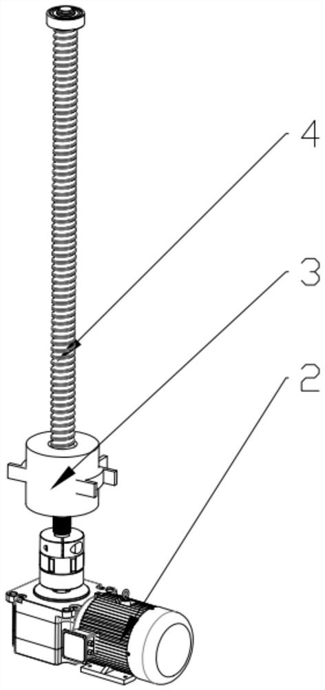
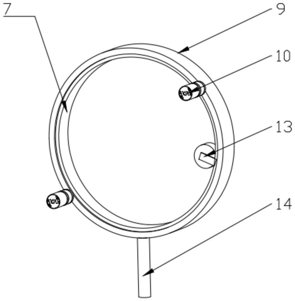
[0023] see Figure 1-6 , according to an embodiment of the present invention, a three-way thermoplastic winding device includes an operating table 1, on which a first stepping motor 2 is fixed, and the rotating shaft of the first stepping motor 2 passes through The connecting assembly is connected with a lead screw 4, the outer wall of the upper end of the lead screw 4 is fixedly provided with a bearing 15, the bearing 15 is fixedly provided with a sliding track 5, and the sliding track 5 is fixedly connected with the inner wall of the console 1, so The sliding sleeve on the outer wall of the sliding track 5 is provided with three first sliders 6, the outer wall of the screw 4 is threaded with a second slider 3, and the first slider 6 is connected to the second slider 3. The brackets are all hinged with sliding links 16, and the second slider 3 is fixed with a telescopic bracket 14, and the upper end of the telescopic bracket 14 is equipped with an automatic winding device, an...

Embodiment 2

[0026] see Figure 1-4 , for the connection assembly, the connection assembly includes a transmission 22 and a shaft coupling 23, the operation table 1 is fixed with a transmission 22, the input shaft of the transmission 22 is connected to the rotating shaft of the first stepper motor 2 Fixedly connected, the output shaft of the transmission 22 is fixedly connected with the lead screw 4 through a coupling 23; for the sliding track 5, the sliding track 5 is provided with a T-shaped structure; for the telescopic support 14, The telescopic brackets 14 are all electric telescopic rods.

[0027] Through the above scheme of the present invention, the first stepping motor 2 can drive the lead screw 4 to rotate through the transmission 22 and the shaft coupling 23, and then can drive the second and second sliders 3 to move along the lead screw 4, The distance between the outer ring 9 and the sliding track 5 can be adjusted by controlling the expansion and contraction of the electric ...

Embodiment 3

[0029] see figure 1 , 2 and 6, for the tee pipe support assembly 12, the tee pipe support assembly 12 includes a cross bar 20, a vertical bar 21 and a support bar 19, and one end of the cross bar 20 is welded and fixed to the inner wall of the upper end of the console 1 , the middle part of the cross bar 20 is plugged with a vertical bar 21, and the outer walls of the horizontal bar 20 and the vertical bar 21 are fixed with a number of telescopic support rods 19; for the sliding link 16, the sliding link The two ends of the rod 16 are respectively hinged with the first slide block 6 and the second slide block 3; for the first step and the first step motor 2, the first step motor 2 is connected to the first step motor 2 through anchor bolts. The console 1 is fixedly connected.

[0030] Through the above solution of the present invention, the cross bar 20 is inserted into the three-way mold 11 , and the vertical bar 21 is inserted on the cross bar 20 , so that the three-way mo...


PUM


Abstract

The invention discloses a cable winding device for three-way thermoplastic. The cable winding device comprises an operation table, wherein a first stepping motor is fixedly arranged on the operation table, a rotating shaft of the first stepping motor is connected with a lead screw through a connecting assembly, the outer wall of the upper end of the lead screw is fixedly sleeved with a bearing, a sliding rail is fixedly arranged on the bearing, the sliding rail is fixedly connected with the inner wall of the operation table, the outer wall of the sliding rail is slidably sleeved with three first sliding blocks, the outer wall of the lead screw is in threaded connection with a second sliding block, and sliding connecting rods are hinged to supports of the first sliding blocks and supports of the second sliding block. The cable winding device has the beneficial effects that three automatic winders are driven by a stepping system of the first stepping motor and a second stepping motor to achieve a winding function, the rotating speed of the stepping system and the rotating speed of the automatic winders are controlled, the distance and the winding time of cables can be controlled, and finished pipe fittings needed by users are obtained.

Description

technical field [0001] The invention relates to the technical field of winding production of three-way thermoplastic molds, in particular to a winding device for three-way thermoplastic molds. Background technique [0002] In the industry, plastic pipe joints are usually processed by injection molding machines. Before processing, cables are wound at the ends of molds such as straight pipes, elbows, and tees. The insulating plastic is melted by heat, and the fittings and pipes are welded together through the melted insulating plastic layer. The traditional winding process is manual winding. In the era of modern technology development, manual winding has disadvantages such as long time-consuming, low efficiency, uncontrollable winding distance, and unsightly winding of finished pipe fittings. Among them, the three-way pipe fittings are more specific and complex in structure than straight-through and elbow pipes. The invention provides a winding device for a cable embedded in...

Claims


Application Information

Patent Timeline
Patent Type & Authority Applications(China)
IPC IPC(8): B65H54/06B65H54/10
CPCB65H54/06B65H54/10B65H2701/34
Inventor 翟璐璐高峰崔宝玲
Owner ZHEJIANG SCI-TECH UNIV
Why Eureka
Try Eureka