Giant magnetostrictive cylinder and rod composite driving electromechanical converter and working method thereof

A giant magnetostrictive rod and giant magnetostrictive technology, applied in the field of hydraulic servo control, can solve the problems of increasing the axial size of the actuator, the large size of the driving structure, and the difficulty in ensuring the accuracy of the bias magnetic field, etc., to achieve thermally induced displacement Compensation function, high thermal displacement control accuracy, and high utilization of the driving magnetic field

Inactive Publication Date: 2013-08-21
NANJING UNIV OF AERONAUTICS & ASTRONAUTICS
View PDF2 Cites 0 Cited by
  • Summary
  • Abstract
  • Description
  • Claims
  • Application Information

AI Technical Summary

Problems solved by technology

[0009] (1) The above drivers adopt double super magnetostrictive cylinder rods arranged axially opposite each other to form a double super magnetostrictive actuator. Although it has the characteristics of large output displacement, it is precisely because of the axially opposed structure that the The axial size of the actuator is not suitable for some special fields such as aerospace, where the axial installation size is limited and the radial size is more flexible;
[0010] (2) Although the above drivers provide a thermal deformation compensation mechanism, there is no cooling and heat dissipation structure design. For thermal deformation displacement control, the thermal deformation compensation mechanism is passive compensation, while the cooling and heat dissipation structure is designed for active control. Therefore, It is difficult to guarantee the reliability of accurate thermal displacement compensation of purely passive thermal deformation compensation mechanism;
[0011] (3) The above drivers are jointly driven by the bias coil and the driving coil, the bias magnetic field is provided by the bias coil, and the driving magnetic field is provided by the driving coil. This driving method has the advantage of convenient adjustment of the bias magnetic field, but due to the large , the number of turns of the bias coil is large, resulting in a large size of the drive structure and serious problems of coil heating. Other similar actuators have a scheme that uses a permanent magnet to provide a bias magnetic field and a drive coil to provide a drive magnetic field, but this drive method It has the disadvantages that the bias magnetic field cannot be adjusted and the accuracy of the bias magnetic field is difficult to guarantee after the permanent magnet is demagnetized;
[0012] To sum up, in the existing double-phase opposed giant magnetostrictive driver, there are disadvantages such as large axial size, severe coil heating, and affecting GMA output accuracy. , small size and other advantages, but the adjustment of the driving magnetic field is inconvenient, especially the demagnetization phenomenon caused by the magnetic drop of the permanent magnet cannot be adjusted in time to affect the GMA control accuracy

Method used


Image

  • Giant magnetostrictive cylinder and rod composite driving electromechanical converter and working method thereof
  • Giant magnetostrictive cylinder and rod composite driving electromechanical converter and working method thereof
  • Giant magnetostrictive cylinder and rod composite driving electromechanical converter and working method thereof

Examples


Embodiment Construction

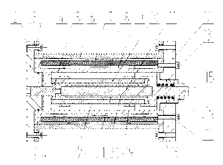
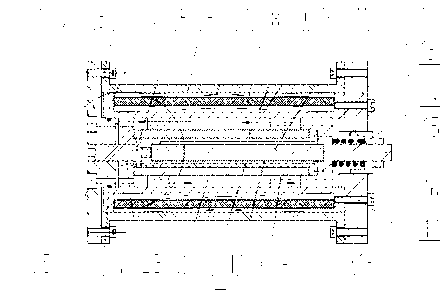
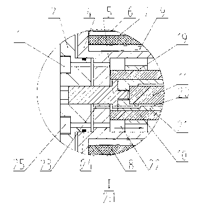
[0038] Such as figure 1 , as shown in 2 and 3, this new type of giant magnetostrictive cylinder rod composite drive motor-machine converter includes outer cover 6, left end cover 2, right end cover 12, thermal compensation plunger 5 installed in the left end cover 2, installed in the right end The output rod 15 in the cover 12, the bobbin 4 installed in the outer cover 6 with one end fixed to the right end cap 12 and the other end leaving a thermal expansion gap with the left end cap 2, the double supermagnet installed in the bobbin 4 through the support ring 19 A telescopic tube rod, and a bias magnetic field generating unit and a driving magnetic field generating unit are installed on the coil frame 4;

[0039] The above-mentioned double giant magnetostrictive rods are sequentially composed of giant magnetostrictive cylinders 10, Z-like force transmission cylinders 21, and giant magnetostrictive rods 11 from outside to inside; the right end of the Z-like force transmission ...


PUM


Abstract

A new type of ultra-magnetic telescopic bar stick composite drive electrical-machine converter, which is the field of microcontroller technology.Including the outer cover (6), the left end cover (2), the right end cover (12), the heat replenishment plunger (5), the output rod (15), the coil skeleton (4), the double ultra -magnetic telescopic cylinder stick, the coil skeleton (4 4) Installation is installed with a unit of the driver magnetic field and the units of the bias magnetic field. Among them, the unit of the driving magnetic field is driven by the driver's magnetic field.The rod radial layout, through the Z-shaped force tube for force and displacement, so as to achieve large micro-displacement; electric-machine converter has large displacement output, small axial size, compact structure, small heating, heat deformation control is reliable, Differential magnetic field adjustment can be widely used in the development of microcontrollers and microcomputers, especially suitable for single or multi-level electrical servo service valve electric-machine converters.

Description

technical field [0001] The invention relates to the application of giant magnetostrictive materials and belongs to the technical field of hydraulic servo control. Background technique [0002] As a bridge connecting its electrical components and hydraulic mechanical components, the electro-mechanical converter is one of the key components of the electro-hydraulic servo valve and even the hydraulic control system. The performance of the electro-mechanical converter is directly related to the performance index of the electro-hydraulic control system, and some indexes are even related to whether the system can be realized. Improving the frequency response and load capacity of the electro-mechanical converter is the prerequisite for improving the frequency response of the electro-hydraulic servo valve. At present, with the development of advanced manufacturing technology, microelectronics technology and the research and development of converters based on new functional material...

Claims


Application Information

Patent Timeline
Patent Type & Authority Patents(China)
IPC IPC(8): H02N2/02
Inventor 朱玉川程清风王晓露李跃松
Owner NANJING UNIV OF AERONAUTICS & ASTRONAUTICS
Why Eureka
Try Eureka