Road engineering seamless bridge deck expansion joint structure and construction method thereof

A technology for road engineering and expansion joints, applied in bridges, bridge construction, bridge parts, etc., can solve the problems of damage to expansion joints, lack of waterproof capability of bridge expansion joints, and difficulty in replacing airbags, so as to improve the ability of protection and absorption, meet the The effect of reducing the difficulty of replacement and maintenance due to the needs of construction and maintenance

Active Publication Date: 2021-06-25
赵方雄
View PDF29 Cites 5 Cited by
  • Summary
  • Abstract
  • Description
  • Claims
  • Application Information

AI Technical Summary

Problems solved by technology

[0004] The purpose of the present invention is: in order to solve the lack of waterproof ability of the bridge expansion joints, the air bag cannot be flushed and erupted after the water liquid is immersed in the air bag, and the axial stress resistance of the air bag to the expansion joint is insufficient, which affects both sides of the expansion joint The ability of shock absorption and buffering makes the expansion joints easy to be damaged by repeated rolling during the driving process of the vehicle. At the same time, it is difficult to replace the airbag, and the top bridge deck needs to be demolished. The road engineering seamless bridge proposed Surface Expansion Joint Structure and Its Construction Method

Method used


Image

  • Road engineering seamless bridge deck expansion joint structure and construction method thereof
  • Road engineering seamless bridge deck expansion joint structure and construction method thereof
  • Road engineering seamless bridge deck expansion joint structure and construction method thereof

Examples


Embodiment approach

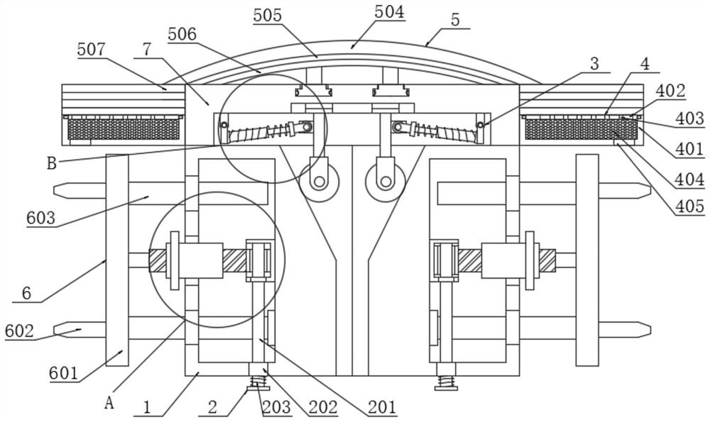
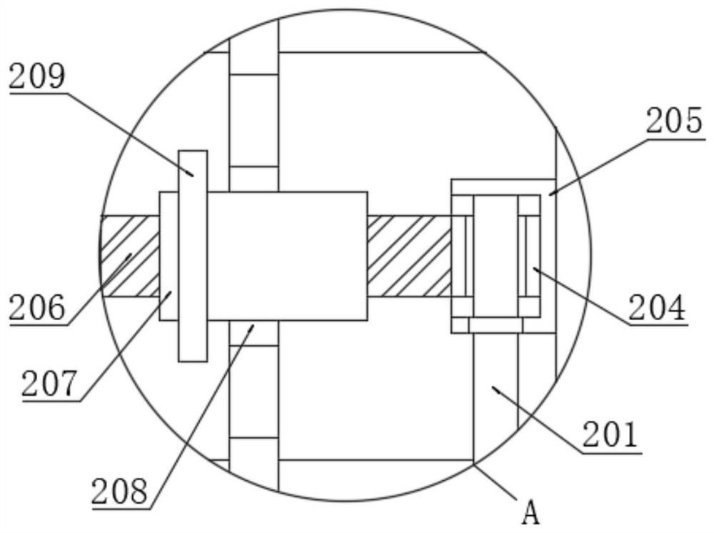
[0044] The implementation method is as follows: the insertion rod is pre-assembled into one side of the bridge deck through the anchor rod 602 on one side and bonded, at this time, the second sliding rod 603 is slid into the second sliding sleeve on the side of the elastic body 1 Close the limit, and screw the threaded column 206 connected to one side of the insert 601 into the threaded cylinder 207. At this time, the threaded cylinder 207 is driven to rotate by turning the handle, and the threaded cylinder 207 rotates to drive the threaded column 206 of the threaded connection to move inwardly The movement of the threaded post 206 can drive one side of the limit block 204 to snap into the limit seat 205. At this time, the second slide bar 603 at the bottom can be pulled upward to reset and snap into the limit block 204, and then the threaded post 206 and the insert The insert 601 is movable and clamped, and then the elastic body 1 and the bridge deck are clamped and limited. A...


PUM


Abstract

The invention discloses a road engineering seamless bridge deck expansion joint structure and a construction method thereof, and belongs to the technical field of road bridge decks. The road engineering seamless bridge deck expansion joint structure comprises a joint cover, elastic bodies are attached to the two sides of the top of the joint cover, limiting mechanisms are arranged in inner cavities of the elastic bodies, one sides of the limiting mechanisms are connected with connecting mechanisms, and damping mechanisms are attached to the tops of the elastic bodies. According to the invention, an inserting rod is pre-assembled into one side of the bridge deck through an anchor rod on one side and attached to one side of the bridge deck, a threaded column connected with one side of the inserting rod is moved into a threaded cylinder to drive a limiting block on one side to be clamped into a limiting base, the relative distance between the elastic bodies and the bridge deck is adjusted, and the bridge deck expansion joint connecting requirement is effectively met; the threaded cylinder and the threaded column can be driven to be separated by screwing a wheel disc, and the threaded column and the limiting base are separated after a first sliding rod is pulled to be separated from the limiting block, so that the disassembly and replacement efficiency of the elastic bodies can be remarkably improved, the replacement and maintenance difficulty is reduced, and the bridge construction and maintenance requirements are met.

Description

technical field [0001] The invention belongs to the technical field of road bridge decks, in particular to a road engineering seamless bridge deck expansion joint structure and a construction method thereof. Background technique [0002] During the construction of the bridge deck, in order to meet the thermal expansion and cold contraction expansion needs of the bridge body, a seam at one end is generally set up to limit the expansion. This is the expansion joint body of the bridge. In order to ensure the tightness and durability of the connection of the expansion joint body Generally, it is necessary to use reinforced concrete to repair and smooth the surface to ensure the durable life. [0003] Chinese patent document CN105839532B discloses a bridge expansion joint, which is arranged in the gap between adjacent beam bodies, including: two special-shaped steel side beams, symmetrically fixed on opposite sides of the gap, and both along the width of the beam body Directiona...

Claims


Application Information

Patent Timeline
Patent Type & Authority Applications(China)
IPC IPC(8): E01D19/06E01D19/08
CPCE01D19/06E01D19/08E01D19/086Y02A30/60
Inventor 杨艳陈是君陈元有
Owner 赵方雄
Why Eureka
Try Eureka